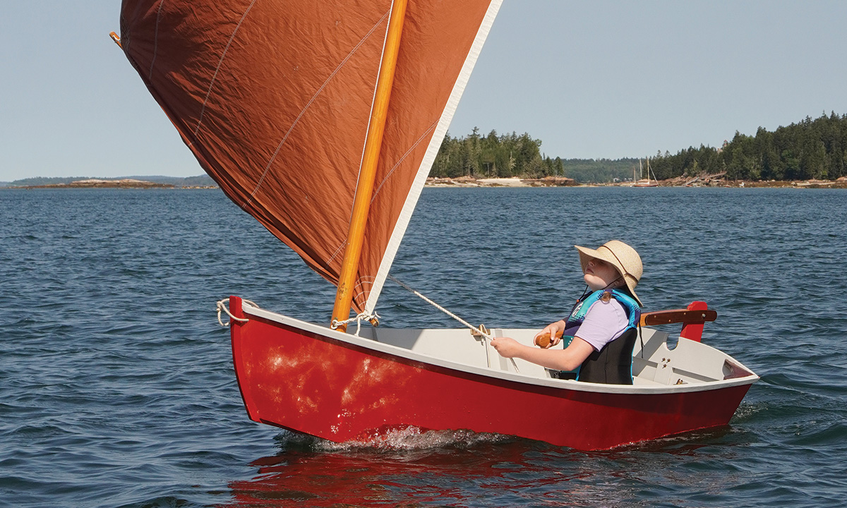
Building Church MouseGreg O’Neil

Building Church Mouse

Part 1: The hull

Introduction

In the mid-1990s, Joel White, of Brooklin Boat Yard in Maine, began designing a simple skiff that could be built of two sheets of plywood without having to scarf them together. His client, a minister in a neighboring town, wanted to build boats with kids. I was building lots of boats with young people around that time, too, and Joel shared a copy of the concept drawing with me before he died in 1997.

After losing that drawing for many years, I found it in spring 2024 and decided to flesh out the design and build the boat. I enlisted the help of Kyle Godfrey, an excellent carpentry and architectural drafting teacher at my local high-school career center in Arlington, Virginia. We used the boat as a project for his carpentry students; the school’s digital arts instructor, Tom O’Day, had his students photograph and video the build. Over two and half months, nine students lofted and built the prototype of what my wife, Jessica, came to call the Church Mouse Skiff, in deference to both its ministerial roots and to the legendary protagonist of Stuart Little, which was written by Joel’s father, E.B. White. We worked out a lot of details during that project. The following summer, I coached the construction of four more of the boats during a one-week Family Boatbuilding class at WoodenBoat School.

The following instructions are a distillation of what we learned building those five boats. Will Sturdy, the chief designer at Brooklin Boat Yard, took all of our notes and scribbles, applied them to his own keen understanding of design and engineering, and created a very thorough set of plans. Those plans are available in both print and digital formats; the print format includes full-sized patterns for certain components, and the digital plans include CNC cutting files. For the sake of accuracy and precision, we urge builders to order the plans in their preferred format and not rely solely on these magazine pages to build this boat. Also, please read and understand the instructions before you start building.

Profile sail planWill Sturdy/Brooklin Boat Yard

Building Church Mouse

Tools

This simple boat can be built entirely with hand tools, but a bandsaw, chopsaw, and tablesaw will vastly ease the work and speed things along. In addition to those, here’s the basic list of tools you’ll need.

Small power tools

  • Jigsaw
  • Circular saw
  • Random-orbit sander
  • Cordless drill/drivers
  • Wallpaper steamer or some other steam source

Hand tools

  • Bench plane
  • Block plane
  • Wood chisel (¾″ or 1″)
  • Files and rasps
  • Tape measure and box rule
  • Combination square
  • Framing square
  • Carpenter’s compass and scribes
  • Center punch
  • Screwdriver (or a brace and bits)
  • Flat-soled spokeshave
  • Utility knife
  • Putty knives
  • Hooked paint pull scraper (for cleanup
    and small adjustments)
  • Toothed plastic squeegees (for applying
    adhesive)
  • Drill bits (including a 6″-long ¼″ bit),
    and countersink
  • Softwood battens, 8′ long,
    ⅜″ × ⅜″ and ¼″ × 1½″
  • • Straightedge, 4′ long (can be made from
    plywood using a factory edge)
  • • A pair of matching sawhorses

Materials

Boat (hull and parts)

  • 2 sheets of 1⁄4″ (6mm) okoume or meranti marine plywood
  • 2″ × 12″ × 12′ clear Douglas-fir for the stem, rubrails, chines, frames, and transom fashion pieces (white oak, or a similar durable hardwood, such as sipo mahogany, are suitable alternatives)
  • 1″ × 8″ × 10′ white or yellow pine for seats (cedar or fir also work well)
  • 1″ × 6″ × 8′ yellow pine (or sipo or oak) for the keel batten and skeg
  • About 3 bd ft of hardwood such as mahogany, oak, or locust for quarter knees, breasthook, and tiller
  • 12 bd ft (minimum) spruce for spars (more, if you’re picking through lumberyard stock)
  • Plastic bagging material of the type used for vacuum-sealing food for storage

Strongback and molds

  • 3- 8′ 2×8s for strongback and transom sled—a jig that holds the transom accurately in place on the strongback. The strongback may be supported on sawhorses or purpose-made legs.
  • 4 × 8 sheet of ⅝″ medium density fiberboard (MDF) or Advantech sheathing, for molds

Fastenings

All fastenings are of silicon bronze or stainless steel:

  • 120 – ⅝″ No. 8 wood screws
  • 100 – 1″ No. 8 wood screws
  • 50 – 1¼″ No. 8 wood screws
  • 50 – 1½″ No. 8 wood screws
  • 10 – 2″ No. 8 wood screws (for seats and keel)
  • 1 – 3½″ machine screw, ¼″ × 20 with washer and nut

A Note on Glues and Fillers

On the first boat, we used Titebond III for joints above the waterline. We also used Sikaflex 291 Long Open Time polyurethane adhesive and sealant for fastening anything that needed gap filling or waterproofing. We used epoxy mixed with wood flour and microballoons to fill any temporary holes. For the Family Boatbuilding class, given safety concerns about epoxy sensitization of children and inexperienced builders, we used Sikaflex for almost everything except for hole filling.

Materials Preparation

Step 1Joe Youcha

Building Church Mouse

1. Select and mill the solid wood before beginning construction, matching the stock’s structure and qualities with its purpose. Start with the pieces that require the straightest grain and longest length; these are the chines and rails. The chines are 1¼″×⅝″. Bevel the top edges 30 degrees, as shown on the plans, to prevent water from pooling, which can promote rot. The rails are 1″×⅝″. Avoid grain runout; a well-designed short boat such as this requires a lot of bend from these pieces, and runout will introduce weak spots; you’ll likely be steam-bending these parts.

Ideally, the stem and frames will be made from the parts of the board that are rift-sawn, meaning the grain is parallel to the wide surface of the board. The fastenings that connect the frames to the seats will then hold the grain together, rather than split it apart. The stem comes out of a 1½″×5½″ × 20″ piece. The dimensions of the frames, which come from ¾″ stock, are shown on the plans. The bevels are indicated on the plans, too; they can be cut now and fine-tuned upon installation, if needed. You can prick through the full-sized patterns with an awl to establish the outlines of these pieces, or use carbon paper, if you can find it. Cut out the inner stem with a bandsaw or jigsaw; fine-tune, if you must, with a block plane. For a finished appearance, lightly bevel the inboard edges of the frames after you rip them.

The transom is made from one layer of 6mm plywood framed by ¾″×2½″ pieces on the sides—called “fashion” pieces—and bottom, and a ¾″×5″ piece across the top. There’s also a ¾″×2″ center transom support that strengthens the transom and provides fastening for the rudder hardware. The side and bottom fashion pieces are beveled; these bevel angles and others are listed in the plans.

The plans show the optimal layout for the plywood parts to get them out of two sheets. You can cut the parts all out at once, before you start building; be sure to arrange them on the plywood panel according to the drawing.

Laying Out the Side Panels

Step 2Will Sturdy/Brooklin Boat Yard

Building Church Mouse

2. The plans show the measurements for the expanded, or unbent, shapes of the sides and bottom; you’ll reproduce these at full size on your plywood panels. To begin, lay your 4′×8′ panel either on the floor or on a surface of 2×4s supported by sawhorses. On the plywood panel, lay out a grid of lines 1′ apart, square to the long factory edge, as shown on the drawing. These lines are called “stations.”

Each station has two measurements taken from the factory edge (which is the “baseline”); one defines the bottom edge of the side panel and the other the top edge, or sheer. After marking these points at each station, partially drive a finish nail at each one. Taking the bottom and top one at a time, spring a ⅜″×⅜″ batten along the nails, then set a few finish nails on the other side of the batten to hold it in place. There shouldn’t be any lumps or bumps in the batten. If there are, shift the batten as little as possible to “fair” the curve. It’s usually better to make a few adjustments at several stations, rather than one big adjustment. Draw the line along the edge of the batten corresponding to the marks. Do the same for the next line. Then, create the other needed points and draw the remaining lines until your plywood looks like the plans.

The measurements for locating the ends of the panels—the stem, and the transom—are also on the plans. There’s also a mark for mold No. 2, which you should transfer to the side panel because it allows you to locate the panel on the jig. Cut out the side with either a jigsaw or a circular saw, staying ¹⁄₁₆″ outside of the line.

Use the first side piece as a mirror-image pattern for the second one. Cut out the second one, then clamp or finish-nail the pieces together with the grid lines visible on the outside. Plane both pieces together to the drawn lines, holding the plane flat and 90 degrees to the surface of the panels. The panels should be identical when you’ve finished.

The bottom panel is similarly marked and cut out. Both the side panels and bottom panel are drawn slightly oversized on the plans, to allow for final trimming after they’re in place.

Cutting the Transom

Step 3aJoe Youcha

Building Church Mouse

Step 3bWill Sturdy/Brooklin Boat Yard

Building Church Mouse

3a & 3b. Use the full-sized drawing to make a half pattern for the inside face of the transom, which is the face with the largest dimensions. I like to use Masonite for patterns, and a nail or awl pricking through the paper works well to transfer the plans to the pattern stock. Connect the dots and draw the outline of the transom on the pattern stock, making sure to also mark the center­line. Cut out the pattern and use it to mark out the transom on its appropriate place on the 6mm 4′×8′ plywood panel. Draw a centerline square to the edge of the plywood and lay the half-pattern on one side of the centerline, and then the other, to develop the transom’s full shape.

Assembling the Transom

Step 4Scarlett Stevens/Arlington Career Center

Building Church Mouse

4 & 5. Solid-wood, beveled fashion and framing pieces reinforce the transom. They create mating surfaces for the sides and bottom and allow for strong screw fastening. Additionally, they allow for a sculling notch at the top of the transom and provide good fastening for the rudder hardware.

Step 5Joe Youcha

Building Church Mouse

Align the top fashion piece with the top edge of the transom and clamp it in place. Its top edge is left straight to make its mounting on the strongback easier; it will receive a graceful crown later. Then clamp the bottom fashion piece in place. Mark the edges of the top and bottom fashion pieces on the transom, and the centerline of the transom on the fashion pieces’ faces and outside edges, then remove them. To fit the side pieces between the bottom and top fashion pieces, lay them into position on the transom and transfer the marks you just made onto them; cut them to fit. Mark the centerline on the stock for the vertical transom backing piece, align it in position on the transom, mark the edge of the top and bottom fashion pieces on it, and cut it to length. Clamp the fashion pieces and center support in place to check their fits, letting the edges overhang the edge of the transom between ¹⁄₁₆″ and ⅛″. Make sure the bevels of the side and bottom pieces are facing the correct way.

Glue and screw the fashion pieces to the transom using ⅝″ No. 8 flat-head wood screws spaced 5″ apart in a zigzag pattern. Sink the heads just barely below the surface of the plywood; these countersinks will be filled with thickened epoxy.

A bevel on the top edge of the bottom fashion piece will ensure that it sheds water; this bevel could be marked and cut before installation, or provide a lesson in chisel work, as shown here.

Building the Strongback

Step 6Will Sturdy/Brooklin Boat Yard

Building Church Mouse

6. Some simple skiffs don’t require a strongback and molds—a so-called building jig—but this shapely boat does. The strongback, detailed in the plans, is built of two straight, flat 2×8s. If either of them has any crown in its edge, this should be placed so it’s facing up; that edge can eventually be planed flat. Place the strongback at about 34″ off the floor, adjusting it to a comfortable working height for your situation. (Kids prefer a lower setup; old backs, a higher one.) It can be mounted on sawhorses or legs, as shown in the plans.

Assemble the strongback’s pieces with 3″ construction screws, but don’t add the corner brace shown in the drawing until you’ve ensured that the assembly is square by measuring its diagonals. After it is square and the corner brace is fastened, check it for twist, and make any corrections with shims under the corners. The top should be dead-flat; when it is, mark the center of each end and snap a chalkline between the two points to mark centerlines on all the strongback’s crosspieces.

Make the Stem Holder

Step 7Will Sturdy/Brooklin Boat Yard

Building Church Mouse

7. The “stem holder” is a 19½″ 2×6 laid flat with a notch 1½″ wide × 4″ deep cut into its forward end to hold the top of the upside-down stem. The notch must be centered and can be cut with a bandsaw or jigsaw. Mark the centerline on the top and aft edge of the stem holder. The forward two crosspieces of the strongback are notched to receive the stem holder to ensure that it is centered on the strongback, flush with its top. Begin cutting the notches with a circular saw whose depth is set to the thickness of the 2×6; a series of close-together cuts can be knocked out with a chisel, and then that same sharp chisel can be used to flatten the bottom of the notch.

Slide the stem holder into place; the back of its notch should be 2⅛″ from the front face of the strongback. (If your notches were a little off, you may need some slight shimming.) Screw the stem holder to the strongback.

Mark the Strongback for Molds

Step 8Will Sturdy/Brooklin Boat Yard

Building Church Mouse

8. To accurately set the molds, it helps to have a string running down the centerline of the strongback. The string will run from the after end of the strongback to the end of the stem holder. Make a ¼″-deep saw cut on the centerline marks on each of the strongback’s cross braces. Drive a nail on the outside of the aftermost crosspiece. Tie a string—mason’s twine is great for this—to the nail and run it to a corresponding nail on the end of the stem holder.

To lay out where the molds land on the strongback, pick one rail of the strongback as your reference edge, and make a mark 40″ back from the forward end of the strongback, as shown on the plans. This is for the center mold, which is mold No. 2. Using a framing square, draw a line square across the strongback on this mark. The locations of the remaining molds are similarly indicated on the plans; mark these using the same method. Make an X just aft of the station 0, station 1, and station 2 mold marks, and forward of the station 3 mold mark.

Making and Locating the Transom Sled

Step 9Will Sturdy/Brooklin Boat Yard

Building Church Mouse

9. The transom sled has horizontal and vertical surfaces formed by 2×8s, which must be dead flat. These are joined together at the proper angle by side gussets of plywood fastened with 1½″ construction screws; the shapes of these gussets are specified in the plans. As shown on the strongback drawing, two 1×4 cleats run horizontally along the sled’s bottom to fasten it to the strongback; a 1×2 cleat runs across the lower edge of the vertical surface to hold the transom at the correct height.

Mark the centerline on the vertical and horizontal centerpieces of the transom sled; this centerline should be drawn on the cleats, too. Refer to the plans to locate the transom sled on the strongback.

Cutting and Attaching the Molds

Step 10Joe Youcha

Building Church Mouse

10. Transfer the mold patterns from the drawing to the piece of ⅝″-thick MDF from which you are making the molds; the layout drawing on page 41 shows the optimal use of this 4×8 sheet. Since this is a flat-bottomed boat with straight-sided sections, I like using a hammer and a nail to transfer the “corners” of the boat onto the MDF and using the factory edge of the MDF as the baseline that will rest on the strongback. Make sure you transfer the marked centerlines and sheerlines from the patterns onto the molds. Bevel the mold edges according to the angles shown on the plans. Also, note that the mold drawing details the notches that will be cut to receive the chine logs; cut these notches after you’ve faired the molds, noting that the notch in mold No. 3 is deeper than the others.

The bottom edges of the molds require cleats for fastening to the strongback; the plans detail 1×2 stock for this. We had 2×2 on hand for the Family Boatbuilding class, so that’s what appears in the photographs.

Carefully align and then screw one edge of the cleat to the bottom forward edge of the mold with 1⅝″ construction screws. Then, using your marks on the mold as a starting point, use a square to transfer the centerlines onto the cleats. Draw them on the top and edge of each cleat.

Place the molds up against the lines you marked for them on the strongback. Make sure they cover the X marks you made on the strongback and make sure the centerlines on the cleats line up with the strongback’s centerline string. Clamp the cleats to the strongback. Then, screw the cleats to the strongback with 3″ construction screws.

Set the Transom Sled and Brace the Molds

Step 11Joe Youcha

Building Church Mouse.

11. Line up the forward edge of the sled’s forward cleat with the line you drew on the strongback. Clamp and then screw the sled to the strongback. One screw per cleat is fine.

The molds must be square to the top surface of the strongback. Use a framing square to ensure this and then brace them in place with 2×4s of appropriate length, with ends cut to 45 degrees so they land properly on the strongback and the face of the mold, as shown. We used single braces in our classes; the drawings indicate pairs of braces, which allows more adjustment for fixing out-of-square molds.

The Outer Stem

Step 12Will Sturdy/Brooklin Boat Yard

Building Church Mouse.

12. This boat has a two-part stem, and you’ve already cut the inner stem from 2×6 stock. The outer stem is laminated from five ⅛″-thick layers of Douglas-fir or similar wood, bent, glued, and clamped to the inner stem—with plastic sheeting on the inner stem to prevent the two pieces from being glued together. When the glue has cured, set the outer stem aside for later use. (If you prefer, the outer stem can be steam-bent from a piece of solid stock on a separate jig.)

Beveling the Inner Stem

Step 13Joe Youcha

Building Church Mouse.

13. Mark the centerline on the inner and outer faces of the stem. Also mark the line indicating the forward face of the first mold, which is mold No. 0 on the plans. Then, mark the line where the stem intersects the top surface of the stem holder, which is labeled “top of ladder frame” on the plans. Finally, mark the sheerline on both sides of the stem.

This is a good time to rough out the stem bevel at 34 degrees—which is close to the correct angle for its top and bottom. The middle will need more wood removed once the stem is in place on the jig. To cut each side’s bevel, you need two lines on the stem. The first is on the stem’s forward face, which should not come to a knife point; instead, leave ¼″ of thickness there, as indicated on the plans. This is best done by setting your combination square to ⅝″ and measuring in from the outside faces to draw lines on each side of the forward face’s centerline. Next, set your combination square to the appropriate depth indicated on the plans, to draw the rabbet lines on the sides of the stem. These two sets of lines indicate the wood you now must remove with a block plane or spokeshave. This is just the initial bevel, so don’t go nuts; the final bevel will be determined with a fairing batten on the boat.

Place the Stem on the Building Jig

Step 14Joe Youcha

Building Church Mouse.

14. Place the inside face of the stem’s lower end against the beveled top edge of the forward mold. Set the upper end of the stem into the stem holder. (Remember, the boat is upside down.) Line up the appropriate line on the inner stem with the top surface of the strongback holder. If the fit in the stem holder is a little loose, clamp it tight. If that doesn’t work, try fitting small wedges on each side of the stem in the holder.

Next, line up the centerline on the stem’s inner face with the centerline on the forward face of the first mold. A screw through the back of the first mold into the stem will hold the stem in place. To drive this screw, drill a pilot hole at an angle you can reach when the boat is finished, because you’re going to have to remove this screw after the boat is planked.

To fasten the stem to the stem holder, you can use a long screw from one side or a bolt running horizontally through the stem holder and the stem. Before you fasten it in place, double-check the distance between the forward face of the first mold and the inside of the stem at the stem holder; it should be 5⅛″.

Set the Transom on the Transom Sled

Step 15Joe Youcha

Building Church Mouse

15. Place the transom on the transom sled. Align the centerline of the transom with the centerline of the sled, and use two 1½″ construction screws, along the centerline, to fasten the transom to the sled. Drive the screws through ¼″ plywood pads or washers to minimize damage to the transom’s surface

Check that the transom is perpendicular to the centerline of the boat by “horning”—that is, measuring out from the transom’s lower corners to the centerline of mold No. 3; the measurements on each side should be equal. Small wedges between the face of the transom sled and the inner face of the transom will adjust the transom’s position on the sled.

Hanging the Side Panels

Step 16Joe Youcha

Building Church Mouse.

16. The side panels were cut out earlier. To place them in the correct position on the building jig, align the mark you made on the side panel for mold No. 2 with the forward edge of that mold. This ensures that the plank is correctly positioned longitudinally. The sheer marks position the plank at the correct height. The side plank, as cut, is slightly oversized; this allows flexibility to accommodate discrepancies in the setup.

A couple of helpers will ease this job, but if you’re working alone, screw temporary blocks to the molds to hold the panels at the correct height. A few drywall screws with plywood pads, as used when fastening the transom to the sled, will temporarily secure the panel at mold No. 2.

Trial-bending the sides provides a final opportunity to ensure that your stem and transom are correctly beveled. If you see any places that need additional planing, remove the plank and make the adjustments; then rehang the plank and double check the bevels. Once you have the bevels all tuned up, drill pilot holes (without a countersink) for the pairs of drywall screws, driven through small plywood pads, that hold the side panels to the molds.

Clamp the plank to the stem and transom. Spring clamps work well on the stem; C-clamps reaching around the plank edges and hooking to the inner edges of the fashion pieces work well on the transom. Countersink gently for fastenings; you want the head of the screw to be just below the surface of the plywood, which is only 6mm thick and it’s easy to over-drive a screw and have it go all the way through the plywood. Draw a reference line that ensures your screws will land in the middle of the fashion pieces’ thickness; figure out the location at the bottom and sheer, then connect those points with a straightedge. When drilling into the transom fashion pieces, drill parallel to the transom face, not 90 degrees to the planking.

Separate the parts and remove any drilling residue from the joint.

Then spread your glue of choice on the stem and transom joints. Don’t overdo it, but cover the faying surfaces enough to ensure some squeeze-out. Put the panels back into position and drive the screws. After the glue sets, trim the plank’s slight excess to make it flush with the forward face of the stem.

Hang the other side plank the same way, and trim the panel ends flush with the forward face of the stem and after face of the transom. Then determine the chine line by making careful saw cuts in the side panels at each mold, to project the bottom edge of the mold to the outside of the side panel. (You’ll be removing much less wood than shown in the photo, because this side panel was cut well oversized.) Spring a batten through the points described by these saw cuts, mark the line, and cut the chine line ⅛″ to ¼″ above that line. (Note the chine lying on top of the molds has been bent ahead of time and is ready for installation; the pre-bending process is described next.)

Pre-bending the Chine Logs

Step 17Joe Youcha

Building Church Mouse.

17. Small boats such as this one can have a lot of shape, and this shape appears especially in the chine logs and rubrails. When selecting chine-log stock, look for straight-grained pieces with as little runout as possible. Douglas-fir or white oak will work for the chine logs, and you might even get away with not steaming Douglas-fir (as we did on the first boat, although it took many hands along with some firm and careful bending). The bending pattern is lifted from the bottom panel. Overbend the stock by an inch or two at each end. The bending jig for our WoodenBoat School class was simply a series of stakes driven firmly into the ground; blocks screwed to a wooden floor or bench work well, too. Our “steambox” was a roll of plastic bagging used to vacuum-seal food for storage. Our steam source was a wallpaper steamer. We soaked our wood with water in the bag over­night before steaming it. Steam the wood for about 40 minutes; the rule of thumb is one inch per hour.

Regardless of your setup, make sure you orient the bevel on the top edge of the chine log correctly; you must end up with one bent for the port side and the other for the starboard side. To achieve this, one bevel should be facing up in the jig, the other down. (In this photo, we were preparing parts for four boats. You’ll only need to steam two chine logs.)

Fitting the Chine Logs

Step 18Joe Youcha

Building Church Mouse.

18. At this point, the chine logs are longer than their finished dimensions; they must be cut to length with beveled ends that fit against the stem and transom. Begin by labeling the chine faces “inside,” “outside,” “up,” and “down.” Then use the bevel gauge to measure the horizontal angle between the side panels and the inside face of the stem, keeping the gauge square to the surface of the panel and not parallel to the ground. Mark this angle on the end of the chine log’s top face. Next, measure the vertical angle between the edge of the panel and the inner face of the stem, and transfer this angle, too; both angles you drew should originate at the same point on the chine. Cut the resulting compound angle; a Japanese pull saw works well for this.

Now butt the chine log against the stem and bend the chine log into the boat. Check the fit against the stem. If it needs further trimming, do that now. When it fits, clamp the forward portion of the chine log tight to the side panel and into the notch of mold No. 2 (the amidships mold). Make a mark on the chine log at the forward edge of mold No. 2 and a corresponding mark on the side panel. Carefully remove the chine log from the boat.

Fitting the Chine Logs at the Transom

Step 19aJoe Youcha

Building Church Mouse.

19 a & b. Now you must pick up the bevels on the chine logs for the transom. Using the bevel gauge, measure the angle between the inner surface of the side panel and the transom, keeping the gauge square to the surface of the panel. Mark it near the end of the chine; the chine will be trimmed to the proper length later. Then measure the vertical angle between the edge of the panel and the face of the transom. Mark this angle on the chine log with the angle originating at the same starting point as the one drawn in the previous step. Cut the compound angle and check the fit.

Step 19bJoe Youcha

Building Church Mouse.

Bend the chine log into the boat starting at the stern. Make sure it fits tightly against the transom and fit it into the notch at mold No. 2. The excess length will extend past the bow; don’t worry about this. Clamp the chine log firmly against the side panel. Find the mark on the side panel that you made when you were fitting the forward portion of the chine log and make a new mark on the chine log corresponding to the mark on the panel. Carefully remove the chine log from the boat.

The distance between the two resulting marks is the amount you must cut off one end of the chine log; you can measure it with a ruler or make a “tick stick” by recording the tick marks on a piece of scrap and transferring the distance between them to one end of the chine log. Using that mark, reconstruct the existing compound angle and make the cut.

Installing the Chine Logs

Step 20aJoe Youcha

Building Church Mouse.

20 a & b. You will need a combination square, 5⁄8″ No. 8 screws, glue, a drill with a countersink, and a screwdriver of choice. I prefer a bit and brace over a power driver, because the brace delivers ample torque with greater control.

Using the combination square as a marking gauge, draw a line on the outside faces of the side panels 5⁄8″ down from the bottom edge. This indicates where to drive fastenings.

Draw a line on the inside face of the panel 11⁄2″ down from its bottom edge; this indicates where to apply adhesive (a short piece of scrap wood between the chine log and the side panel near the transom will minimize the smearing of adhesive until the piece is in its final position). After the glue is spread, take the after end of the chine log and run it down toward the floor and back toward the transom (see 20b, below). This will allow you room to fit the chine log’s forward end into the boat. Then slide the chine log forward until it fits the stem. Finally, raise up the aft end of the chine log until it fits the transom.

Step 20bIsaac Robbins, After Joe Youcha

Building Church Mouse.

Align the inside edge of the chine log with the inside edge of the transom. Clamp the chine log in place. It will stand proud and be planed to fit the bottom later.

Working one side at a time, starting at the center mold (No. 2), drill pilot holes 5″ apart through the plywood side panel into the chine log, working toward both ends. Forward of mold No. 2, drill the pilot holes in a slight zigzag pattern above and below the fastening line, and aft of mold No. 2 locate the screws just below the fastening line to keep the screws below the finished outside edge that will be planed to accept the bottom. With the holes finished, start from the middle and work toward both ends to drive ⅝″ No. 8 screws to fasten the sides to the chine logs. Install the second chine log the same way.

Preparing for Bottom Panel Installation

Step 21Scarlett Stevens/Arlington Career Center

Building Church Mouse.

21. The objective of this step is to plane the chine logs, stem heel, and transom flat so the bottom panel will bear fully on them; the better the fit, the less likely the leaks. You’ll need a 4′ straightedge and a sharp plane. Don’t plane 90 degrees to the side. Hold the plane so its sole is parallel to the horizontal edges of the molds. Using the straightedge, check that both chine log edges are flat and match this plane; there should be no gaps on the inside or outside edges, and no rounding. When planing the transom, work toward the centerline from the ends, because if you run all the way across, you’ll split out the plywood on the far side. Trim the end of the stem if necessary. A rasp, file, or hooked paint scraper works well for small adjustments.

Preparing and Installing the Bottom Panel

Step 22Scarlett Stevens/Arlington Career Center

Building Church Mouse.

22, 23. If you haven’t already, rough-cut the bottom panel to the dimensions shown in the plans, put it on the boat, trace where it meets the side panels and the transom, and then cut it out. Stay slightly outside the traced line.

After cutting, double-check that the panel fits tightly to the chine logs, stem, and transom. Make several reference marks, take it off once more, and apply adhesive to the chines (including the edge of the side panels), stem, and transom. Put the bottom back on, align it with the after edge of the transom, allowing an even overhang on each side. Then, temporarily fasten the bottom into the chines at both ends of the center mold, the transom, and the stem with finish nails. Drive the nails so that they just pin the bottom in place. Don’t sink them!

Step 23Joe Youcha

Building Church Mouse.

Make a finger gauge as shown in the drawing above from a scrap piece of plywood, or even stiff cardboard. Sometimes called a feeler gauge, or jump stick, this device is designed to reach around the excess bottom plywood that’s hanging over the edge of the boat so that a line can be marked on the bottom as a reference for driving screws in the middle of the chine log’s thickness.

Using the length of the finger gauge to indicate the distance, space screws every 5″ along your fastening line, staggered so that they land between the screws that fasten the sides to the chine logs. Use your judgment, because the flare of the sides changes and the finger gauge is made for an average angle. Clean adhesive off the finger gauge as it builds up.

Drill countersunk pilot holes and fasten with 1″ No. 8 screws. Work both sides toward the same end, then go back to the middle and do the same toward the other end to avoid creating any humps in the bottom. The pilot holes and screws should be set parallel to the side panels (not perpendicular to the bottom) Remove temporary finish nails as you proceed. If you have two teams of “fasteners,” have them work on opposite sides of the boat.

Trim the Bottom Flush to the Sides

Step 24Scarlett Stevens/Arlington Career Center

Building Church Mouse.

24. When the glue has cured, cut the bead of squeeze out with a utility knife, and use a block plane to do the final trimming of the bottom panel’s edges.

Mark the Inside of the Plank Panels

Step 25Joe Youcha

Building Church Mouse.

25. Trace the edges of each mold onto the inside faces of the side panels, and at the same time transfer the sheerline reference line from each mold onto the sides. The photograph below was taken after the boat was taken off the molds, but it clearly shows the desired marks.

Make and Install Cross Spalls

Step 26Isaac Robbins, After Joe Youcha

Building Church Mouse.

26. When you take the boat off the molds, it will change shape unless you first install three temporary spreaders, or “cross spalls.” The first should be placed between molds No. 1 and 2; the second right next to mold No. 2; and the third between molds No. 2 and No. 3. Place them so they are clear of any of the diagonal mold braces; otherwise, you won’t be able to lift the boat off the molds. The cross spalls, ideally, should be placed 4″ below the sheer; they can be made from any appropriate piece of solid wood; 1×4s, 2×2s, or 2×4s work well.

To pattern the cross spalls, use two strips of ¼″×1½″ plywood held together with hot-melt glue, and two more short tabs on the ends of this pattern, hot-melt-glued to the proper angle. Record the horizontal angle on the pattern.

To cut the cross spall, lay each pattern on the cross-spall stock and draw the end lines. Then draw the end angles you recorded on the edges of the stock. Make the cuts by hand, or with a bandsaw or jigsaw. Make sure you know whether it’s an under bevel, (where your line is the long point of the piece) or a standing bevel (where your line indicates the shorter face of the piece). It determines how you make the cut.

Put the cross spalls in their final positions and draw their outlines on the inside of the boat. Drill a small pilot hole, without a countersink, from the inside through the side planking. This indicates where you need to fasten the spreader in place with a temporary drywall screw driven through a small plywood pad from the outside. The photo below shows the installed cross spalls.

Remove the Hull from the Molds

Steps 27 & 28Joe Youcha (both)

Building Church Mouse.

27 & 28. Remove the screws holding the boat to the molds and transom sled. Also remove the one from the stem holder into the stem, which can only be accessed from the inside. Then, carefully lift the boat off the molds, set it right-side up on a pair of sawhorses, celebrate your accomplishment, and get ready to complete your Church Mouse Skiff as described in the next issue.

Fairing the Building Jig

Fairing, in this case, means making sure that the faying surfaces of the molds, transom, and stem will have full contact with the planking and introduce no lumps or bumps in the hull. We’ll fine-tune the molds’ edge bevels now so they support the thin planking and have no sharp corners that could damage or weaken it. Gluing surfaces at the stem and transom should be flat, not rounded.

The basic fairing tools are a good batten, sharp planes, and a fine rasp. A good, straight-grained, softwood batten is sacred: no nails should go through it, and it doesn’t get cut up for paint-stirring sticks. The batten should be between ¼″ and ⅜″ thick to mimic the thickness of the plywood. To fair molds, I like a batten that’s 1½″ to 2″ wide, although you can get away with one that’s as narrow as ½″.

Beveling the molds, stem, and transom is an exercise in subtraction. When the batten touches one edge of a mold, the gap between it and the other edge of the mold is the amount you need to remove from the edge that touches the batten. The batten must touch the molds, the stem, or the transom at the same time. Fair the bottom as well as the sides. For trimming the end-grain on the stem’s heel, a fine rasp works well.

Here’s a trick of the trade you can use here and in many other places: when planing across end-grain, such as the tops of the frames, use a rasp to bevel the far edge of the surface to the line; this will prevent that edge from splintering out when you switch to the plane.

When fairing, press the batten to the boat only where you have a piece of the boat to press against. I generally fair from amidships toward the ends. I check the chine, sheer, and halfway in between as I make any “subtractions.” Pay particular attention to the stem and transom. Having two people for this process is very helpful. If you’re doing it by yourself, you’ll have to clamp the batten to the mold either by fastening a cleat a few inches from the mold’s edge or cutting an appropriate-sized hole in the mold with a hole saw.

When the fairing is complete, cut the notches in the molds so that you can insert the chines. Make your notches in molds Nos. 1 and 2 1″×2″. In mold No. 3, the notch must be 4″ deep to allow the chine to be deflected while working it into place.

Article ends.


Joe Youcha is a lifelong educator and boatbuilder. He is the former executive director of The Alexandria Seaport Foundation (www.alexandriaseaport.org), co-founder of the Teaching With Small Boats Alliance (www.teachingwithsmallboats.org), and founder of Building To Teach (www.buildingtoteach.com), which trains teachers in hands-on math instruction.

For WoodenBoat School’s Family Boatbuilding Week, July 19-25, 2026, Joe Youcha will teach five families how to build Church Mouse. For more details, visit www.thewoodenboatschool.com.

Plans for Church Mouse are available from The WoodenBoat Store, www.woodenboatstore.com.