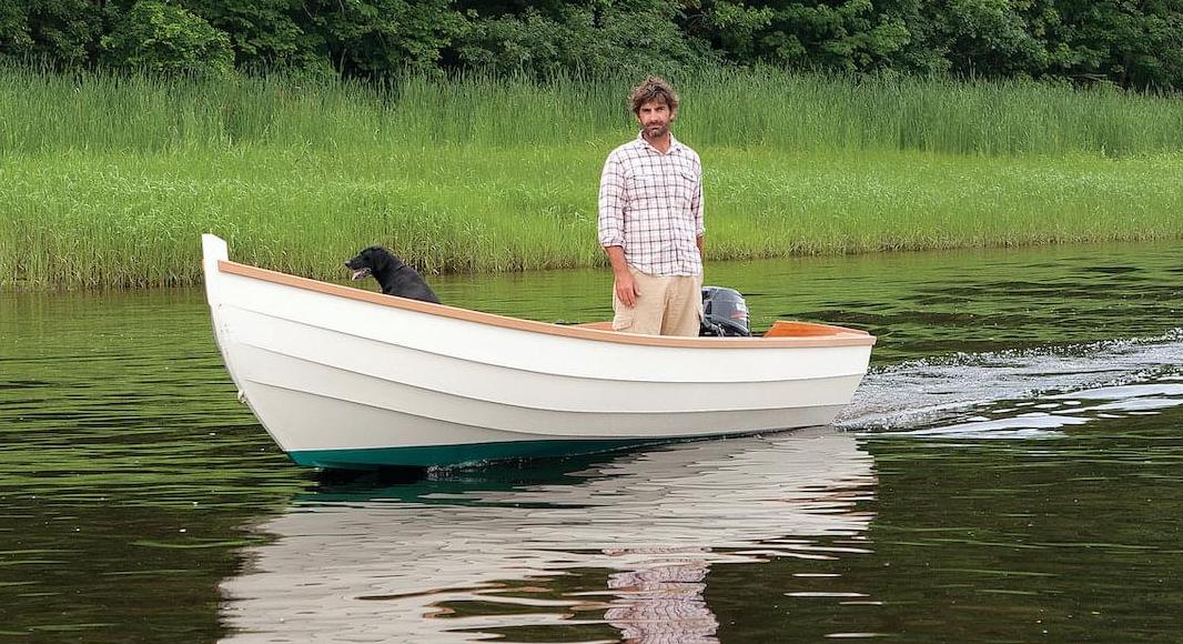
The Amesbury Skiff is a classic outboard powered workboat derived from the dories of the Massachusetts North Shore. It is also an ideal recreational boat—great for exploring, fishing, and family outings.
Planking
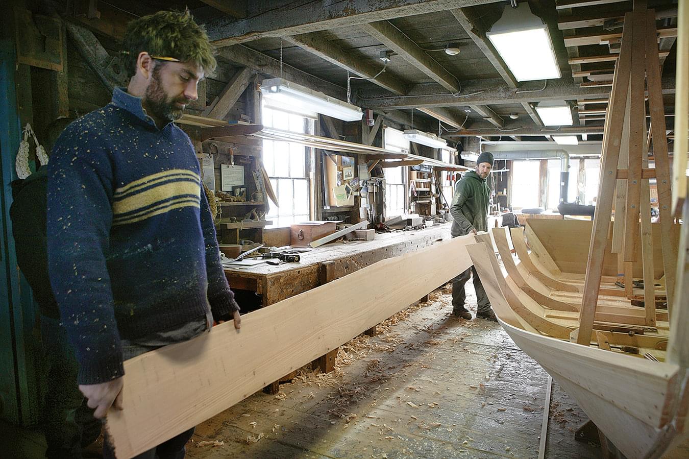
The first plank, as with almost any flat-bottomed boat, is the garboard. These planks are wide, requiring 18″ stock. If they were to be cut from a single straight plank of pine or cedar, there would be considerable grain runout, and the planks would most certainly split. For that reason, Amesbury Skiff garboards have always been made from 1⁄2″ marine plywood.
It just so happens that two lengths of 8′-long plywood joined with a 10:1 feather scarf provide the builder with just enough length for a garboard. The garboards, when laid out flat on round-sided dories and skiffs such as this, typically resemble a pronounced frown; the shape of the bottom and angle at which the garboard meets the bottom determine the amount of this frown.
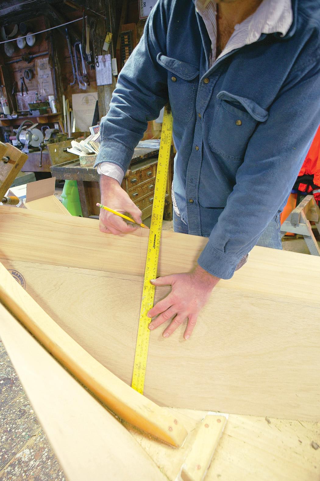
The shapes of these planks are determined by a process called spiling, and spiling planks on dories is right out of the Spiling for Dummies book. On Lowell boats, the shape of a plank is defined by two factors. The first is a series of “lining measurements,” which are plank widths measured vertically up from the boat’s bottom at the base of the stem, the midpoint, and the base of the transom. These dimensions are given on the plans.
The second factor determining the shape of a plank is where the edge of the plank below it lies—or where the edge of the bottom lies in the case of the garboard. To begin spiling, clamp your garboard blank onto the boat so it overlaps the bottom and has enough material along its top edge to accommodate the three lining measurements. Now mark your plank widths on the stock; the forward width (F1) is 13 1⁄2″, the middle width (M1) is 10 1⁄2″, and the aft width (A1) is 11″. To reiterate: Lining measurements are taken vertically; if you measure along the stem and transom, a banana shaped boat will result. With the garboard stock still clamped onto the skillet, trace the inside and outside of the bottom, stem, and transom onto it.
Trace the frames as well to help in clamping the plank back in the correct position. Having fully marked up the inboard face of your plank, you can now remove it and lay it flat on the bench with the markings facing up. Hunt down your best batten—for this process you’ll want one that’s 18′ long, 1″ wide, and 9⁄16″ thick—and strike a fair curve around the three points you marked for the top edge. (You may need to tweak the ends of the batten beyond your F and A points to obtain a nice fair curve.)
The plank’s top edge is now officially spiled. Cut out the plank by whatever method you see fit. I freehand the cut on a tablesaw with a long outfeed table, but you can also use a portable circular saw or a bandsaw. Make sure to cut a little outside the lines, and clean the edges up at the bench with a plane—except for where the garboard overlaps the bottom. I suggest letting that joint overlap by about 1⁄4″, and then planing off the excess when the boat is complete. I also leave the ends a bit long and trim them once the plank has been fastened.
Plank Bevels
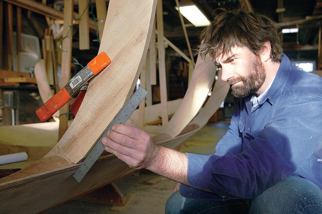
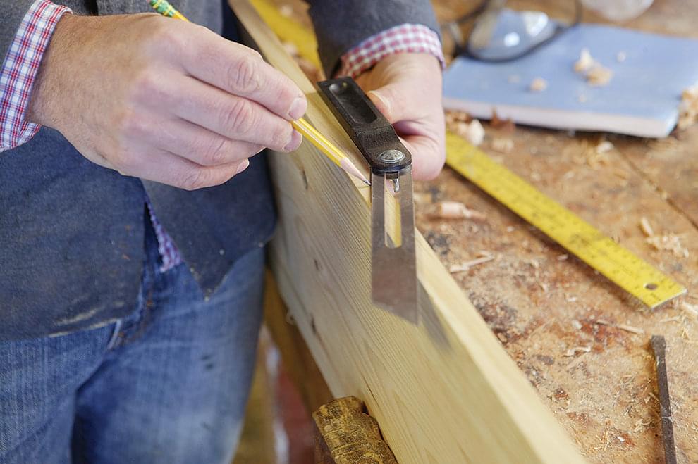
With the plank cut out and its top edge planed to the spiled line, it’s time to lay out the edge bevel. This boat is built with dory laps, which means both edges of mating planks are beveled where they overlap. The top outside edge of each plank (except at the sheer) gets what we call a “standard bevel,” which is 1″ wide by half the plank thickness.
There is also a 3′-long “gain” at each end of the standard bevel—the gain being the tapering of the bevel that allows the laps to appear flush at the stem and transom. To lay out gains, I simply use a yard stick to measure 3′ in from the stem and transom and then draw a 3′ inclined line from my “half thickness” to a feathered tip at the end of the plank.
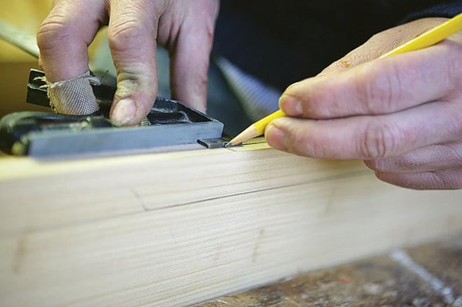
I then plane the sloping bevel, being extra careful to not go beyond the 1″ line marking the width of the bevel. When using plywood for the garboard, I can never see a line drawn on the edge of the plank because the plies obscure it. But I can use those plies to advantage. The 1⁄2″ plywood that I typically use is made up of nine plies, so I plane the bevel until I’ve exposed four-and-a-half plies and their lines are straight along the bevel, indicating there are no humps or bumps.
To make the gain, I begin 3′ from the stem and transom and visually work a gain into the bevel using the plies similarly as a gauge for the incline. Once beveled, the garboard is ready to be hung. Clamp it on the boat once more to check the fit all along the bottom edge and at the stem and transom. Adjust as necessary and then gather a bunch of 2 1⁄2″ No. 10 bronze ring nails, a Forstner bit as big as the heads of these nails, a 6″ × 1⁄8″ drill bit, a hammer, and a nail set.
You’ll also need to make a jig for marking the fastening locations. I use a piece of scrap with one straight edge, and cut out a notch in it such that the straight edge can be laid on the outside of the boat’s bottom and clear the overhang of the garboard, leaving about 2″ outboard of the garboard. This jig projects the plane of the bottom to the outside of the garboard.
Mark 7⁄16″ up from where the jig hits the garboard, and drive nails horizontally into the edge of the bottom using the Forstner bit to countersink the heads. A lubberly job is apparent when nails are poking through the inside of the bottom.
A good way to assure success—or, at least, to practice is to first drive nails only at each cleat and frame, so any errors are hidden. Drive the rest of the fastenings when the boat has been turned upside down and the garboard planed flush. These boats were designed and built before modern light high-horsepower outboards could push them along at breakneck speeds through a 2′ chop. Traditionally, luting, or a tiny caulking seam, would have been enough to seal the seam between the bottom and garboard. However, if you plan to hang anything more than a 15-hp engine on your boat I would suggest using polysulfide adhesive sealant.
If you do this, you’ll have to fully fasten the plank with nails every 3″ before the goo cures. Be careful to keep the garboard from creeping down as you fasten it. I will typically start with the plank about 1⁄8″ above its lines, knowing that the fastenings will tend to pull it down as they are driven home. I use 2 1⁄2″ nails into the bottom, 2″ nails into the transom, and 1 1⁄2″ nails into the stem. The nails at the stem should be about 2″ apart, fall right at the bearding line, and be driven perpendicular to the plank face.
With the garboard planks hung and fastened, trim their after ends flush with the transom. The forward ends are trimmed at an angle so the outboard faces of the planks are longer than the inboard faces; this ensures that you will have enough material when you dress the hood ends before installing the false stem.
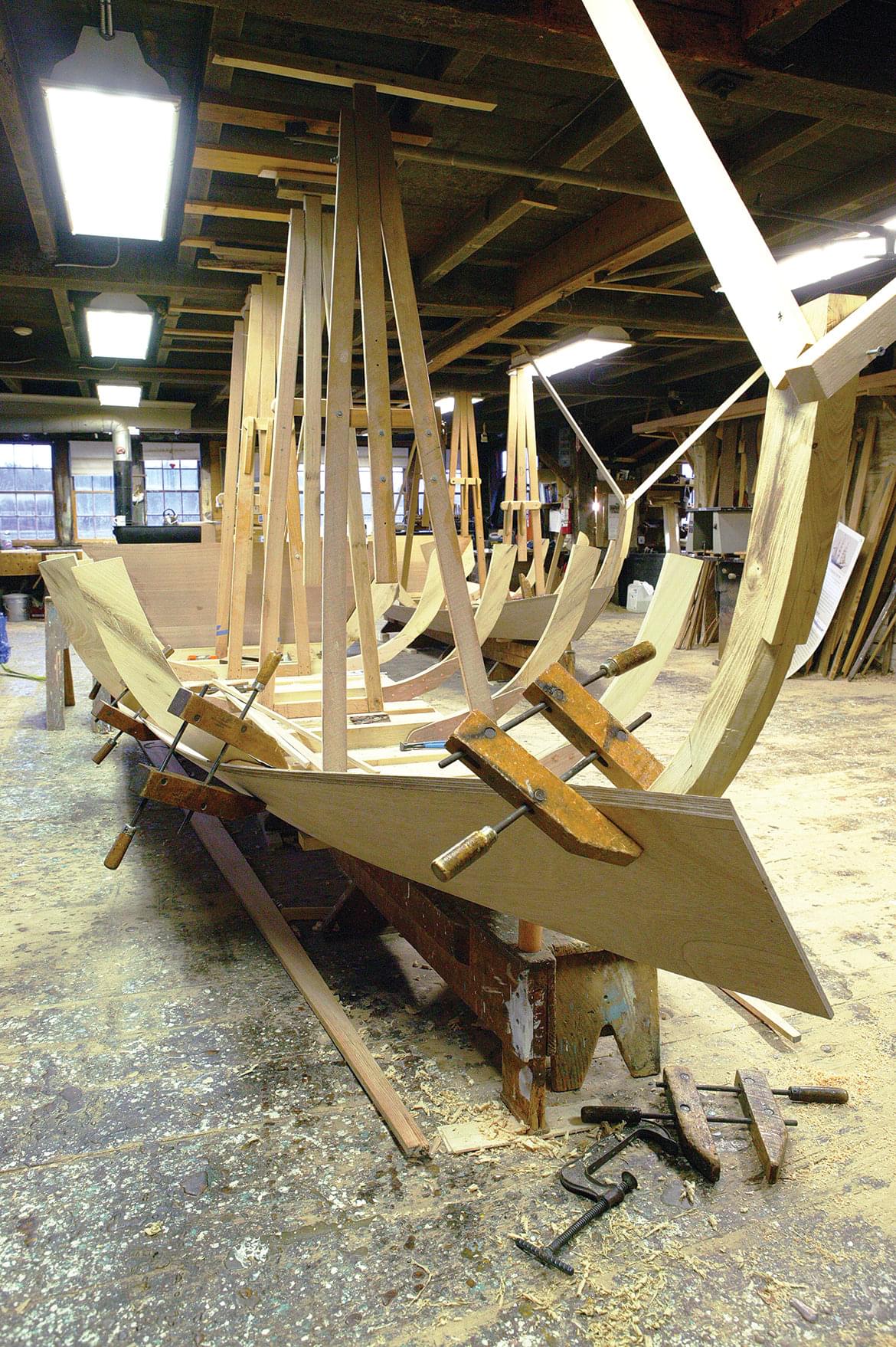
Timber Cuts
On most boats at Lowell’s, frames are initially cut oversize and then trimmed to accommodate planking as the boat is planked. This trimming process is called a timber cut, and the Amesbury Skiff requires these cuts. They follow vague rules depending upon the boat; for the Amesbury Skiff, the rules are pretty straightforward.
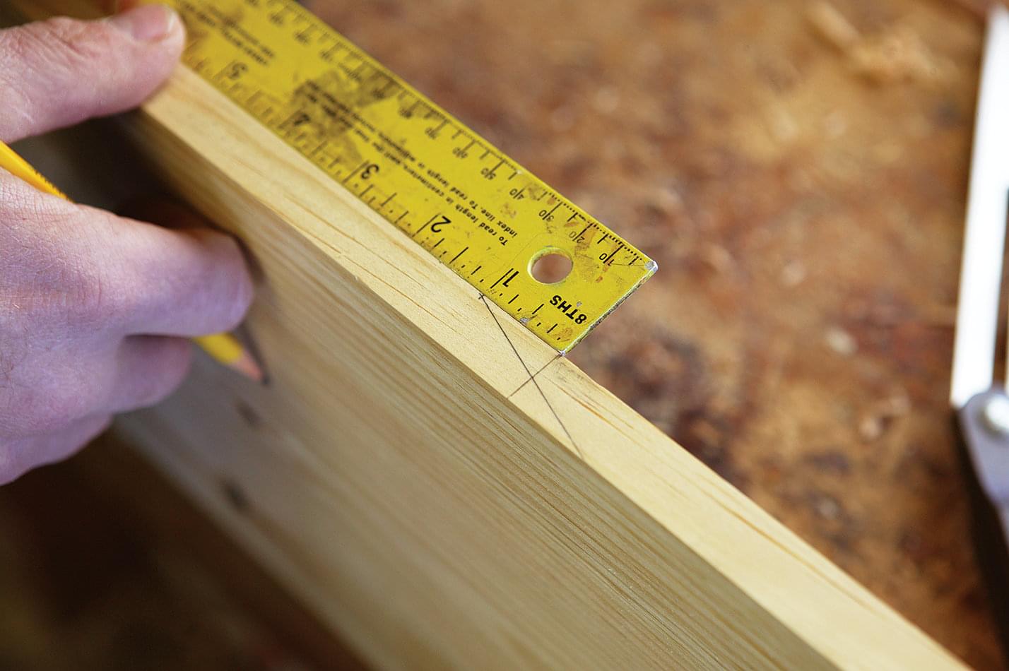
The first rule is for the plank above the garboard the broadstrake and it is a so-called standard cut. At Lowell’s, a standard timber cut refers to a straight line drawn from the top of the bevel of a plank below to a point on the frame where the 10″ mark on a ruler intersects the outside edge of the frame. For the first cut you will end up taking very little of the frame away. I always mark on the after side of the frame, as the shape of this boat dictates that more is trimmed away from the forward side of the frame than from the after side.
When laying out timber cuts, I like to clamp rulers at each frame and at the transom and use my eye to check the overall fairness of the cuts before actually cutting. In the Amesbury Skiff, the frames show a gradual flare from the middle of the boat forward to the stem; the aftermost frame and the transom have parallel timber cuts. Don’t get too caught up with the 10″-mark rule; it’s more important that the cuts look fair relative to each other than the timber cut be exactly at the 10″ mark. Once marked, trim the frame to the line using power planer, bench plane, and spokeshave.
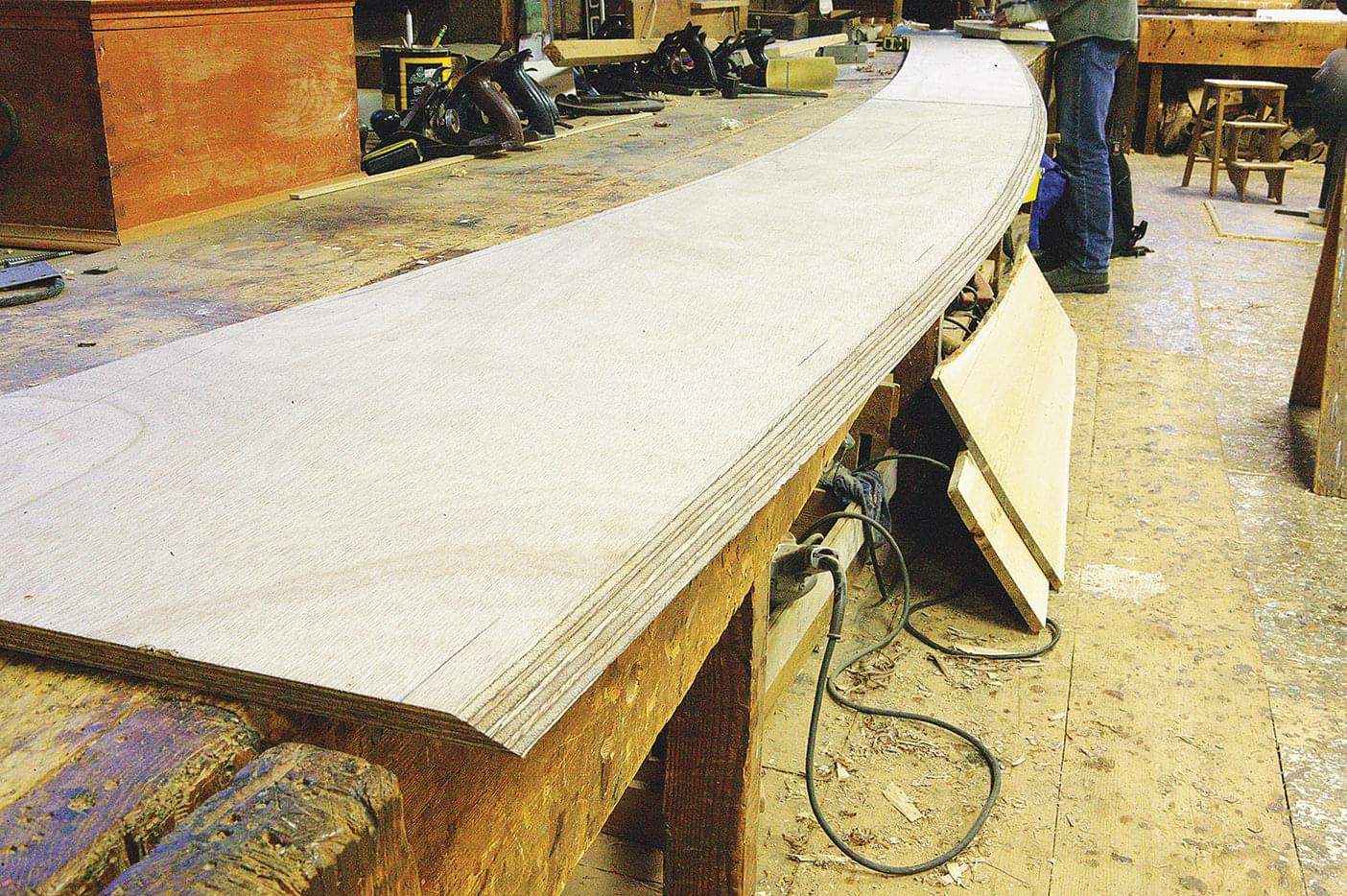
Spiling Subsequent Planks
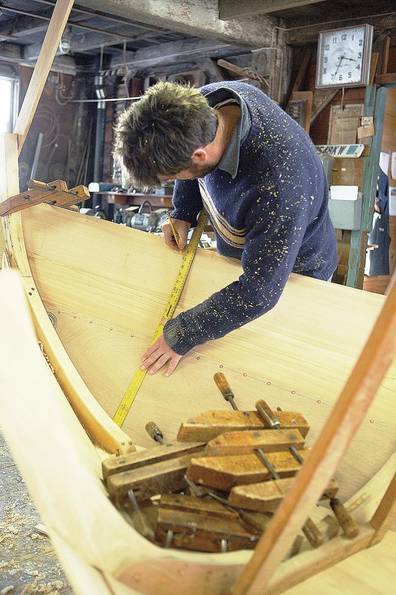
As with the garboard, spiling planks on Lowell boats is very simple. The first step is to get out plank stock 5⁄8″ thick and wide enough (inside the sapwood of course) to cover the 1″ lap on the plank below and reach the marked plank widths forward, amidships, and aft. Clamp the plank to the boat to confirm you have enough stock all around. I usually push the plank up until I barely have the lap covered. At this point, mark your plank widths vertically, with your tape measure bent along the curvature of the planking, from the base of the stem (F1 on the drawings in the previous issue), at the midpoint of the boat (M1), and at base of the transom (A1). This being the second plank, I will add the widths for garboard and second plank and use that sum as the measurement from the bottom, rather than measuring widths from the top of the garboard—which would compound any errors.
Once you’re assured that you have enough wood for the second plank, trace the top edge of the garboard onto it, making sure your pencil is at a right angle to the new plank’s face. Also mark the locations of frames, stem, and transom. Remove the plank from the boat and place it on the bench, inside face up, just as you did with the garboard, with the bottom edge of the plank toward you. Using a 1″-wide batten, transfer the line traced from the top of the garboard down 1″ to account for the lap. To establish the top edge of the plank, use your long batten to connect the three points you marked there with a fair curve. Cut out the plank and plane down to the lines without taking them away, trusting your eye to sight for any high or low spots.
Bevels, Revisited
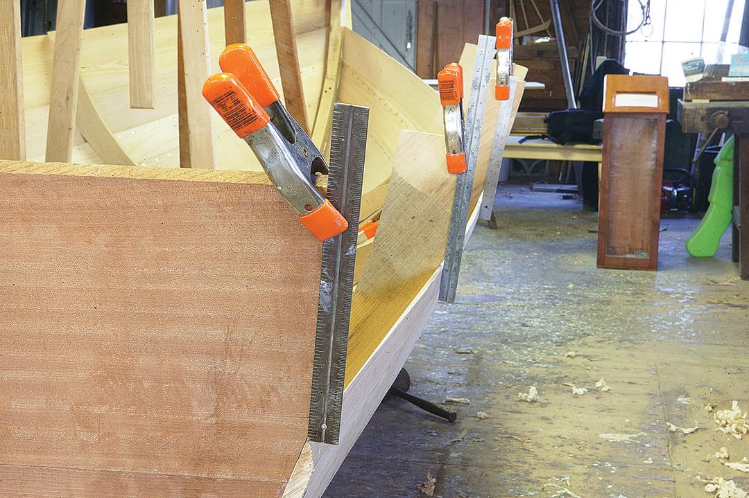
The middle planks require bevels on each edge: the standard bevel on the top outside edge of the plank and a bevel on the lower inside edge of the plank to match the standard bevel that was cut on the garboard. I’ve already described the standard bevel in the discussion of the garboard. The process for the matching bevel is more difficult to explain, so bear with me.
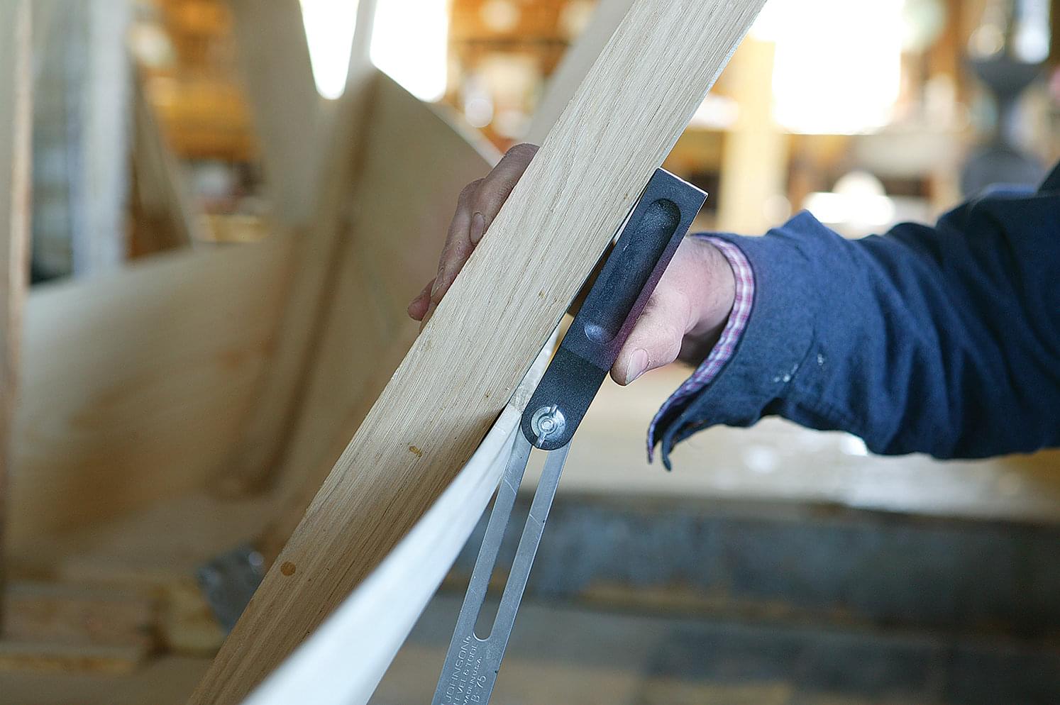
Using a bevel gauge, take the angle between a frame and the bevel you are trying to match. Note that the second plank does not lie against the frame for its whole width, so the idea is to lay the handle of the bevel gauge to mimic the plank’s position. Place the gauge on the boat so the corner of its handle is against the frame, while the gauge’s opposite end—the rounded end with the wing nut—is at the upper corner of the lap (not the upper inside corner of the plank). With the handle thus positioned, adjust the blade so it lies flat along the garboard’s standard bevel, and lock it there. There should be a little triangular gap between the bevel gauge’s handle and the frame.
Take the bevel gauge to the corresponding frame marked on your plank and lay the handle flat on the plank, parallel with the lap, with the blade against the edge of the plank. Using the blade as a guide, draw an inclined line originating between the marks representing the frame, across the plank’s edge. (The location of this inclined line is somewhat arbitrary, for moving it several inches in either direction results in only a negligible discrepancy in the bevel you’ll soon be cutting.)
Next, measure 1″ along the plank’s edge in the same direction in which the inclined line slopes, and mark a point; then draw a line square along the plank’s edge from this point. The point at which the two lines intersect is the limit of your matching bevel in that location. Repeat this process at each frame and connect the intersections with a straightedge to create a continuous line on the edge of the plank. (During the spiling process, you already drew a line on the plank’s inside face to represent the 1″ lap width.)
Use the same process to determine the bevel at the stem and transom, which will automatically provide you with a gain. With your matching bevel now laid out, go to town with slick, drawknife, plane, and whatever else works for you. Lay out and cut a standard bevel on the top outside edge of the second plank before trying it on the boat. This will save you going back to the bench should your matching bevel fit perfectly on the first try. If it does, call me and tell me how you did it!
Fastening
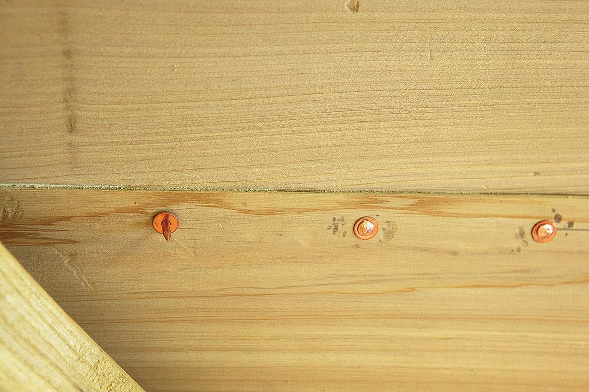
When the plank fits and the bevels are tight when pressed together, it’s almost time to clamp and fasten the plank. But before doing so, I lay out my rivet locations on the inner face of the plank I’m fastening to by drawing a line 1⁄2″ down from, and parallel to, its top edge. Then, along this line every 3″ between frames, I mark a rivet location. I then clamp the plank to the frames and put two rivets between each frame, first making sure the 1″ line drawn for the matching bevel is just barely visible above the plank below. With the middle part of the plank tacked on, I clamp the ends in place and fasten them into the transom with 2″ bronze ring nails and into the stem at the bearding line with 1 1⁄2″ ring nails. With the plank fully tacked on, I’ll then go back and plumb all of the frames before driving a 2″ ring nail through the lap and into each frame.
More Timber Cuts
Using the bevel on the second plank (aka the broadstrake), lay out the timber cuts for the next plank. For this particular plank, the timber cuts are what we at Lowell’s would call “up with the lap,” which means that a straightedge laid across the standard bevel on the plank just hung projects the line for the next timber cut onto the frame.
Just as before, I advise setting up all of the cuts with a short straightedge clamped to each frame, and then eyeing them all together for fairness. The cuts should show an increasing flare forward, while the transom cut should be parallel to the cut on the aftermost frame. (Due to the gain at the transom, timber-cutting the transom “up with the lap” would result in a pronounced tumblehome in the after three planks.)
Binder Plank
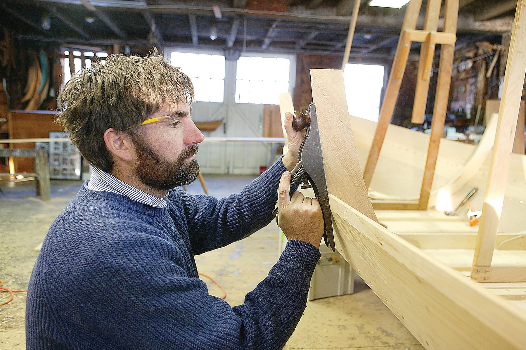
With the timber cuts complete, it is time to spile as before. This third plank is the straightest of all. Therefore, you can plan on using your straightest piece of stock for it.
Clamp your stock (i.e., the plank blank) at each frame and ensure there is enough overlap. Mark your designated plank widths and trace the top edge of the plank below, just as you did earlier. Lay the new plank on the bench and move the traced line down 1″ with a batten, then strike a fair curve through your three plank-width marks along the top edge.
The matching bevel on this plank is simpler than that on the plank below it; since the timber cuts are “up with the lap,” the plank will not require beveling except for the gains at each end, the amount of bevel for the gains being determined the same as it was for the previous plank. As before, lay out and cut a standard bevel into the top outside edge of the plank, test the fit, adjust bevels at stem and transom, if necessary, and prepare to fasten. (Note that when adjusting the stem bevel on boats such as this with pronounced stem curvature, it is often necessary to plane a flat landing along the bearding line to achieve a good fit and keep from splitting the plank.)
Timber Cuts for the Sheer Plank
As with the binder plank, the timber cuts for the sheer plank are “up with the lap” at all of the frames. This again should result in a gradually increasing flare toward the bow. The transom cut, again, is parallel to that of the aftermost frame. The stem should not have any bevel in it yet where the sheer plank lands; it’s most accurate to determine this bevel with the sheer plank clamped in place, fitting the top of the plank into the stem so the stem head remains square above it.
Spile the sheer plank using the plank widths on the plans, and with the plank clamped in place mark the sheerline on all frames, stem, and transom. Again remove the plank from the boat, tack a batten on the boat along the sheer marks, and sight it from many angles to make sure it looks right. Adjust as necessary, then transfer any adjustments back to the plank before cutting it out. Lay out and cut the matching bevels at the gains before clamping the plank back up.
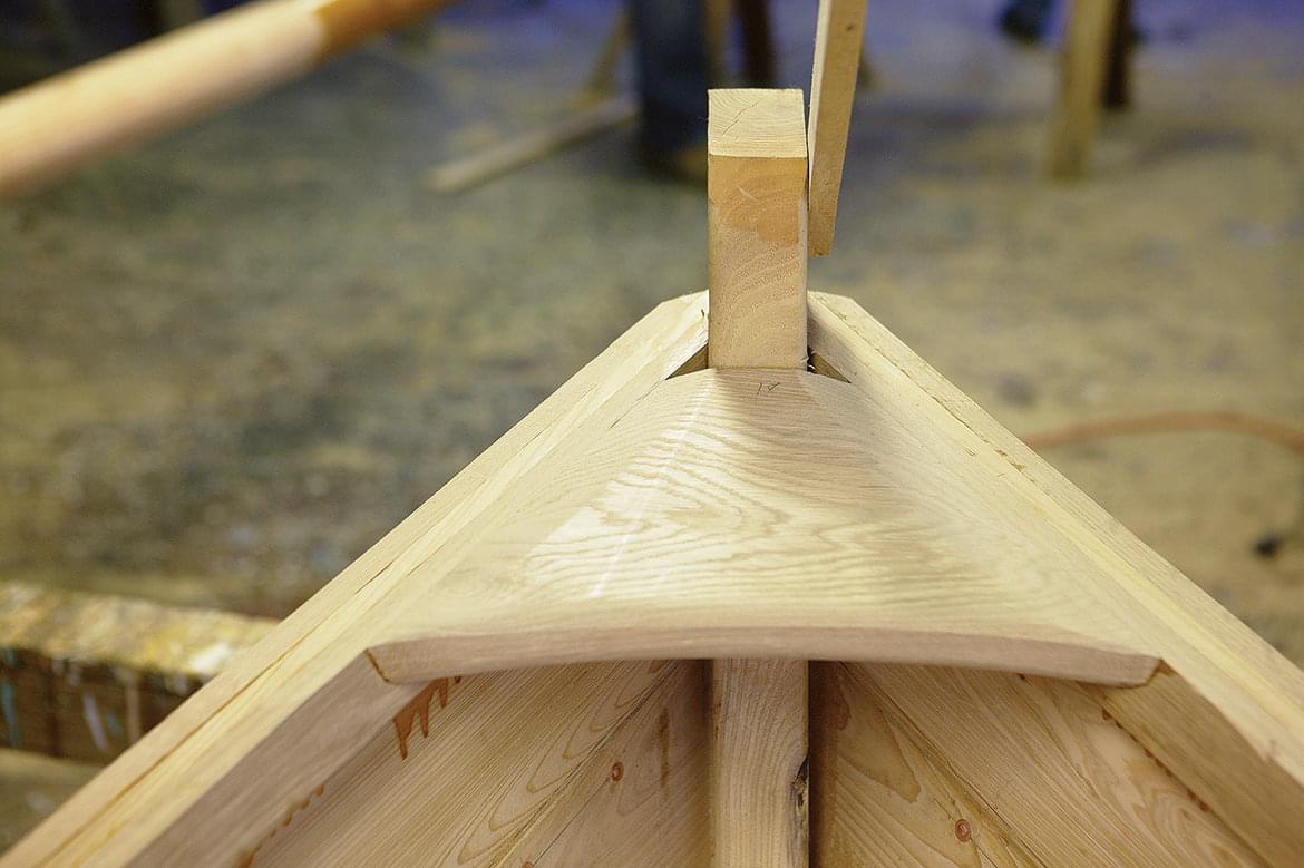
Now fit the refined sheer plank to the stem. Once the plank is fastened, transfer the sheer heights across to the other side of the boat to guide in spiling the opposite sheer plank, and bevel the stem to match the first side but leave a little extra wood at the top of the stem to allow for fitting. Also, leave extra material on the top of the sheer plank to assure a proper fit into the stem and allow for any discrepancies.
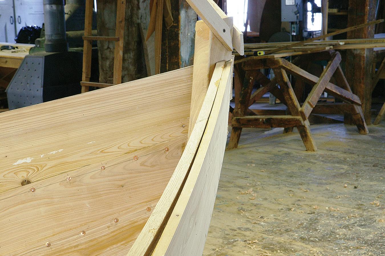
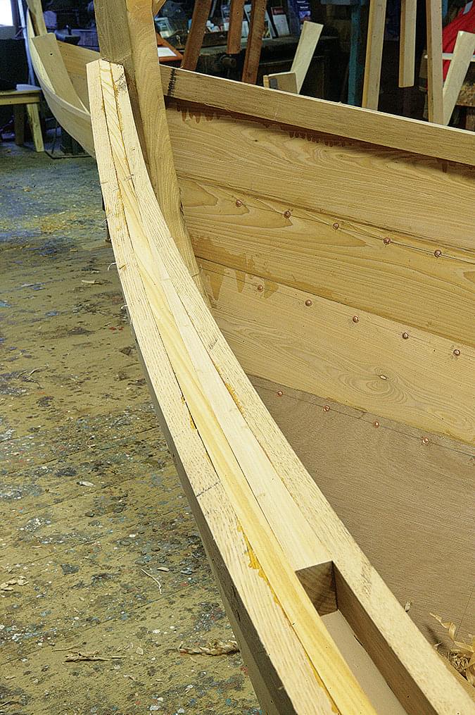
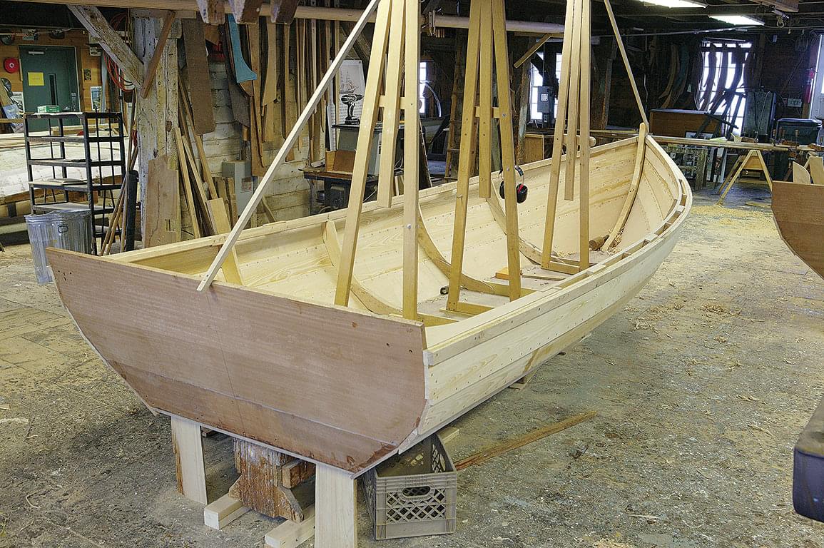
Inwale and Outwale (Rails)
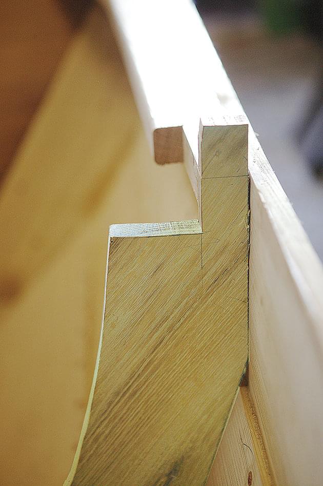
With planking complete, it’s time to fit the rails. But before they can be fitted, you’ll need to install quarter knees—the pieces that strengthen the connection between the sheerstrakes and the transom. I fit these knees square to the inside faces of the sheerstrakes and notch their forward legs to accept the inwale.
At Lowell’s Boat Shop, we give our Amesbury Skiffs elongated quarter knees that run from the transom all the way to the aftermost frame, which distributes the forces on the transom over a wide area and provides a good landing for cleats, running lights, and such. Amesbury Skiffs get a “double rail” (as we call them at Lowell’s), meaning that there is an outside rail, sometimes called an out-wale, and an inboard rail, often known as an inwale. The inwale is fitted by cutting notches into the frame heads so the 5⁄8″ × 1 5⁄8″ rail stands off the sheer plank 1 1⁄4″ with its top flush with the top of the sheer plank.
I use a square to project the top of the sheer plank across the frame head and position the notch in relation to that line. A precise fit at the ends of the inwale is a mark of good craftsmanship, and achieving this can be a trying experience. Patience will pay off, however. Start by fitting the forward end into the V-shaped notch between the stem and sheer plank.
With that end fit, clamp the rail tightly in place against the plank for about one-third the distance from the stem to the first frame. Then let the rail rest in the frame head notches and carefully fit its aft end into the notch you made in the quarter knee. Before final fitting, round over the rail’s lower inside corner so it feels pleasant to the hand.
Tack the rail in place at the frames with 1 1⁄2″ ring nails driven into the lower half of the rail perpendicular to the grain of the frame head (about a 30-degree down angle). I avoid using screws in the frame heads, as they tend to split to the tops of the frames. Leave the rest of the inwale unfastened until the outer rail is in place.
With the inwale tacked in place, wrap the outer rail around the top of the sheer plank and clamp it in place. I find it easiest to leave the corners of this rail square for now, and to run a router around them after the rail is fastened. Rivet through the upper half of the outer rail, the sheer plank, the frame head, and inwale at each frame. Fasten through all at the quarter knees, and screw the ends of the outer rail into the transom and stem.
At this point, make wedges out of scrap plank stock about 2–3′ long and fit them between the inwale and sheer plank up forward and rivet through all. It will be obvious at this stage that some extra support is needed between the frames. Fit 8″ oak blocks midway between the frame heads and, as before, rivet through all. The final step in installing the rails is fitting the breasthook, which should be laid out with the grain running athwartship and cut so it bears evenly on both of the inwales as well as the after face of the stem. I fit and fasten the breasthook leaving it proud of the inwale by about 1⁄4″ so that it can be faired into the angle of the sheer.
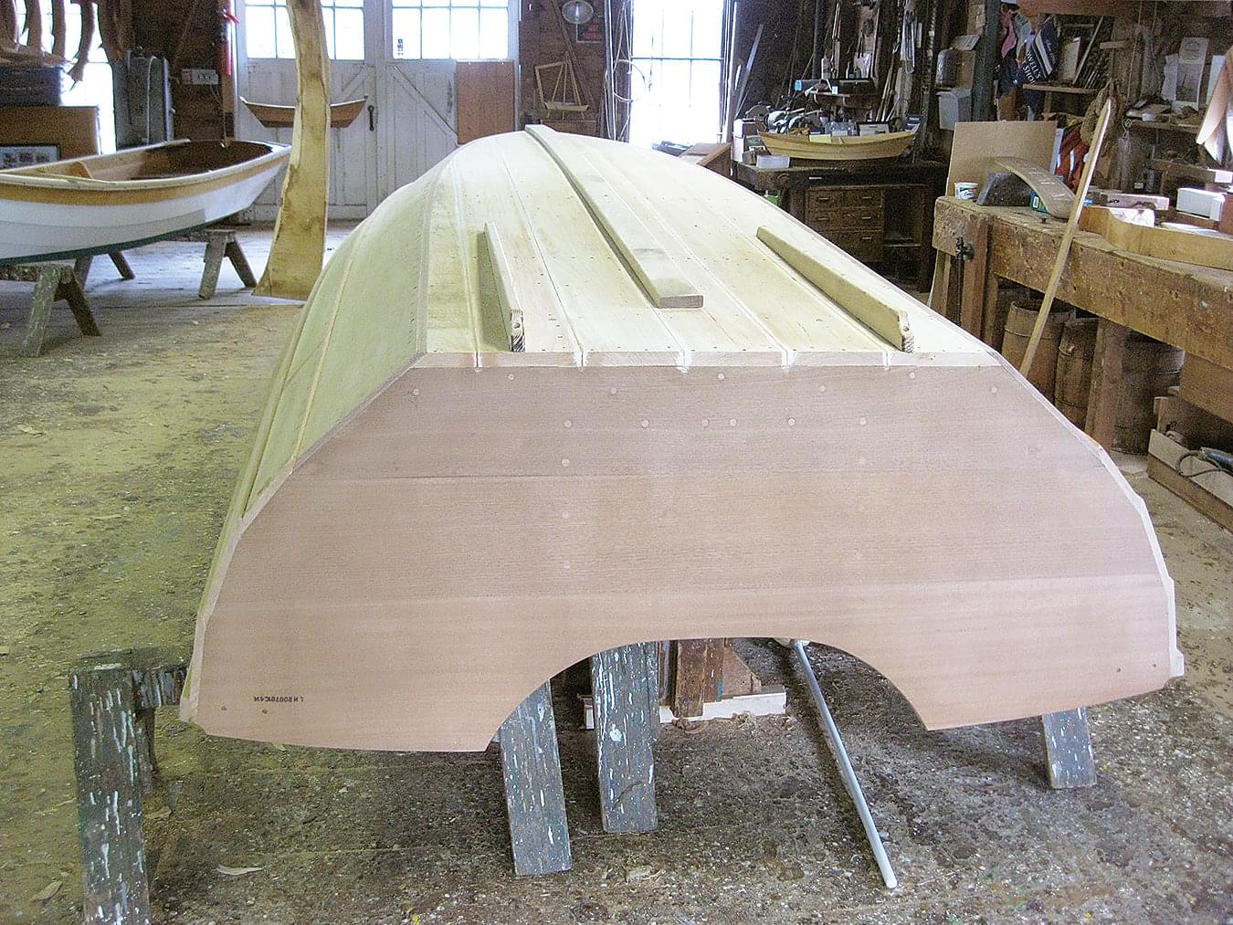
Transom
Finishing the transom requires a scoop-out for the out- board motor, a transom pad, and knees to beef up the structure. The standard transom height for short-shaft motors is 15″, measured from the outside of the bot- tom, and for long-shaft motors it’s 20″. I recommend a long-shaft for these boats to keep water from slapping in over the transom when backing down. Once you have cut out the scoop for the appropriate shaft length, you will need to install a 26″-wide pad to reinforce the transom where the motor lands on it.
Use oak, locust, or some other appropriate hardwood placed with the grain running perpendicular to the transom. Bed the pad in epoxy or other compound and mechanically fasten it with 1 1⁄2″ No. 12 wood screws. The final operation is to install two knees at the out- board edges of the pad. These knees are notched over the aftermost bottom cleat and are riveted through it and the bottom of the boat.
They are likewise fastened through both the transom and pad with 3″ No. 14 bronze screws. Finish the top edge of the transom as desired, making sure you leave enough room in the scoop-out for the engine to fully articulate.
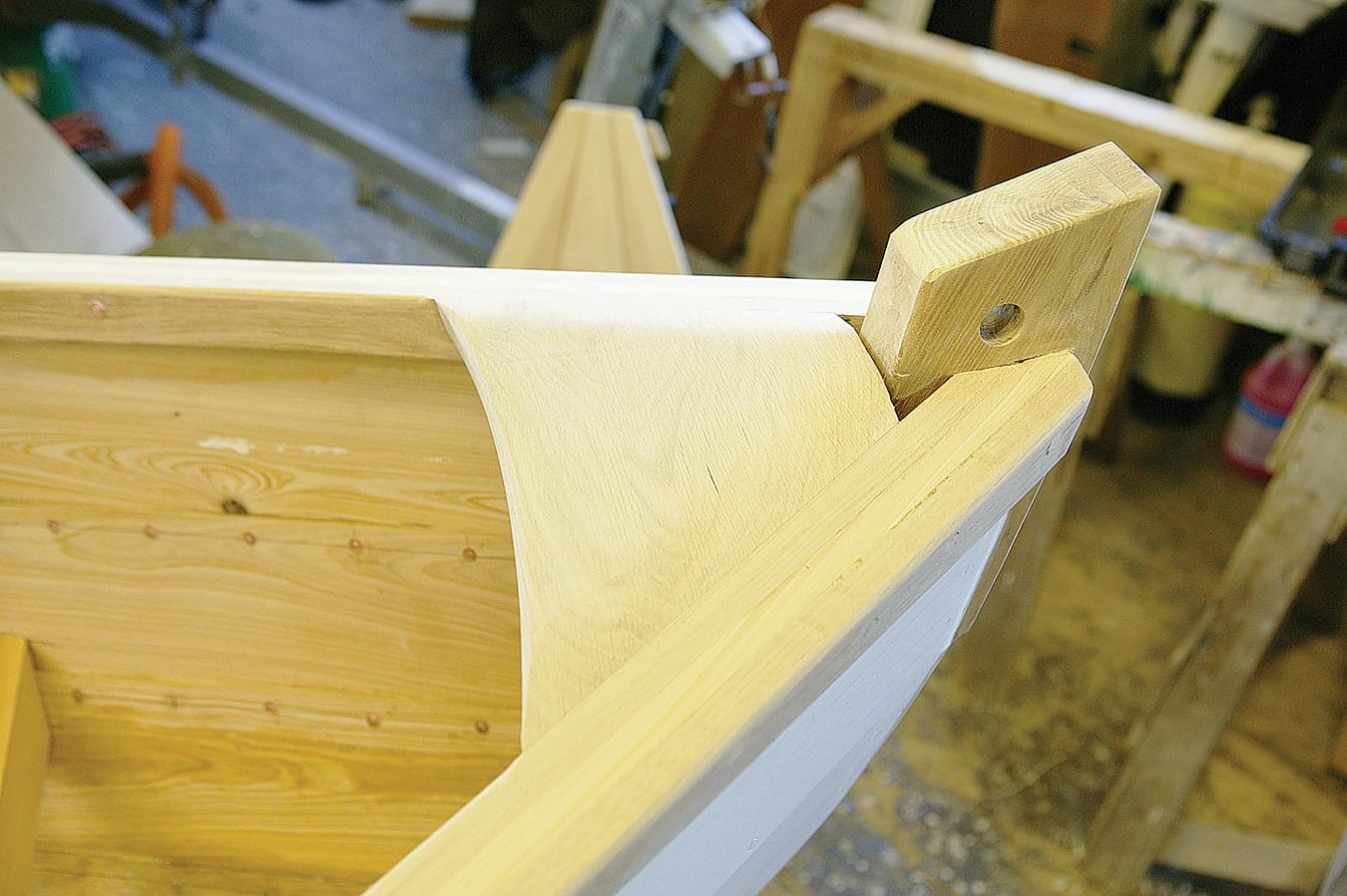
Thwart Risers
Before fitting the thwart risers, you must fair (or dub) the inside edges of the frames so the risers will lie flat across them. I also round the tops of the frames into the inwales, as shown in the photograph. The risers are typically cut from leftover 5⁄8″ planking stock or a piece that was too narrow for planking. The finished width of these pieces is 3″, and the riser has so little sweep that a straight piece of stock can be persuaded into place by edge-setting. I start with a piece of 6″-wide stock long enough to span all of the frames and overhang the for- ward and after ones by about 6″. I rip this piece down its middle with the tablesaw set at 33°, which yields both the port and starboard risers in a single cut.
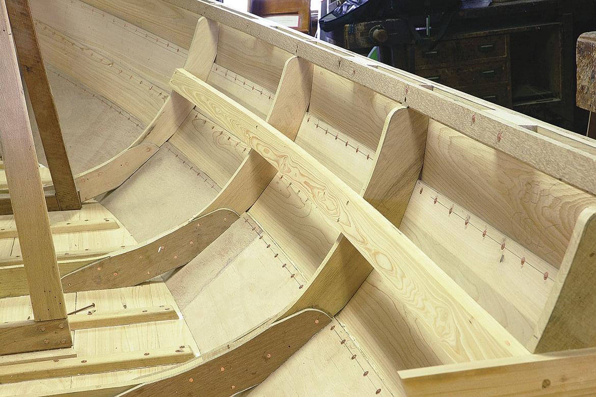
Mark the riser heights down from the top of the inwale at each frame, as shown on the drawing in the previous issue, and screw in the risers working from the middle to the ends. The 33° angle should be facing up to create a flat on which the thwarts will land.
Seating
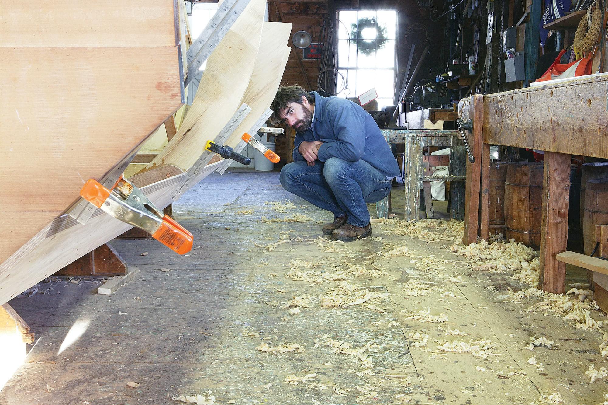
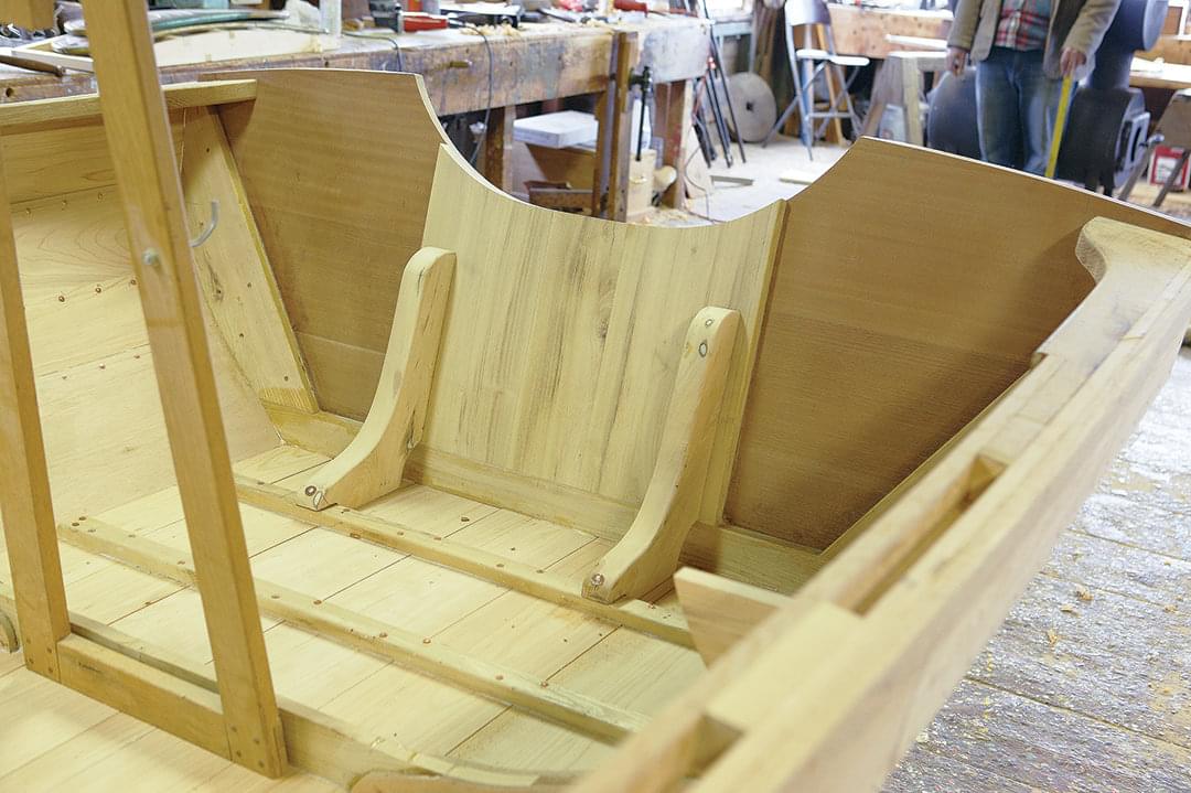
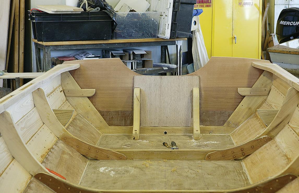
Seating in Amesbury Skiffs varies depending upon the owner’s preference. The basic seating plan involves athwartship seats, called thwarts, at the F and AM frames, and saddle seats between the transom and after- most frame. (The photo at right shows the framework for these saddle seats in a plywood-bottomed skiff.) A typical variation is to install a foredeck forward of the foremost frame at seat level along with a bulkhead at that frame, leaving room beneath for a locker. Feel free to make up your own scheme, keeping in mind that the boat is beamy enough to allow for a center console.
Fitting the athwartship seats is a simple process in dories and skiffs such as this one. Lay out and mark the width of the seat on the top of the seat riser. Then use story sticks to find the length of each seat. (Story sticks for fitting seats are strips of wood the thickness of the seat with 45-degree angles cut in each end.) Lay the lengths out on your seat stock to create a symmetrical seat.
Undercut the ends at 33° and lay out the notches for the frames. To cut the notches, set the tablesaw blade a little less than its full height and carefully free- hand a series of saw kerfs to remove the material for the notch. The seats may require further fitting, but using this method should get you well within the ballpark.
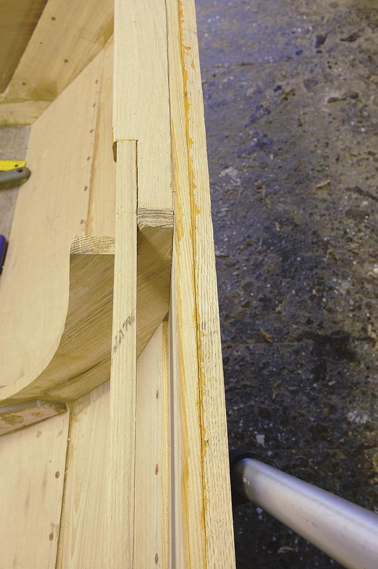
Bottom
With the interior now complete, the boat can be freed from all bracing and removed from the building bed. With the help of five of your best friends, roll the boat over and trim the garboard flush with the bottom, minding any stray nailheads. Reset any nails that stick out beyond the face of the garboard.
Trim the hood ends at the stem flush with its face, making sure they remain square to the centerline. If the hood ends are trimmed too far, the outer stem will not seat properly. Caulk the bottom seams and, when painting over the caulking, dribble some paint into the gap between the garboard and the bottom.
Putty all the seams as well as the small gap between garboard and bottom and the nail heads in the garboard. Fit the two small skegs that should lie 13″ off the centerline and, if you see fit, run a full-length runner, or keel strip, down the middle of the bottom to give the boat a little extra traction.
False Stem
The hood ends at the stem are covered with a false stem, which is a piece of 5⁄8″-thick stock of the same material as the stem. The width of this piece is to be the same as the thickness of the stem so that stem and false stem are flush with each other above the sheerline. The bend in the false stem can be too much to ask of a piece of dry oak, so I cut out the strip and let it soak in the river overnight. The wood doesn’t absorb too much water in this short time, but usually emerges sufficiently limber to bend into place. Clamp the false stem to the stem head and slowly wrap it into place while bracing it by whatever means suit your setup. Let it dry overnight.
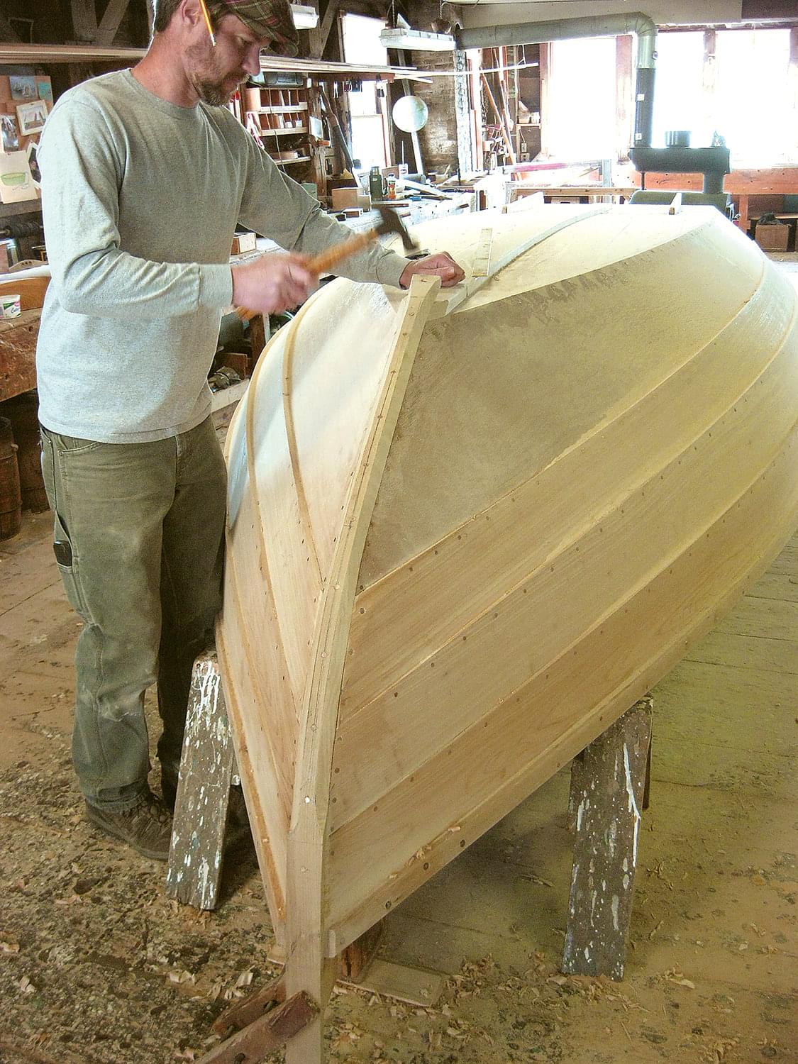
Before fastening the false stem, lay out a centerline on its face and mark for nails every 5″. The hood ends should be first sealed with paint, and the false stem bedded in an appropriate compound or epoxy before installing. To fasten the false stem, clamp it at the stem head and start fastening with 2″ ring nails, beginning at the sheer plank and working toward the bottom of the boat.
After the boat is turned right-side up, deter- mine how you want to finish the stem head. (The standard Lowell’s stem head is cut off three fingers up from the sheerline.) Fasten the portion of false stem above the sheer plank with two pair of 1 1⁄2″ ring nails side by side set about 3⁄8″ in from the edges. Once the false stem is fastened, fair it into the planking. I typically leave the false stem square from the bottom of the sheer plank to the top of the stem head.
Finishing Touches
As with any wooden boat, there are endless finishing touches one can add. The boat we built on these pages received two coats of primer inside and out, then two coats of yacht enamel. The mahogany transom was finished bright, and the similarly varnished locust transom pad contrasts beautifully against it.
I would highly recommend a small center console just aft of the FM frame. The Amesbury Skiff we use at Lowell’s is fitted with a 25-hp four-stroke motor, which gets her up on a plane with little effort. Mind the dif- fering weight of outboards when considering power for your skiff, as you may find that a 30-hp weighs far more than a 25. The converse may even be true.
Amesbury Skiffs are tried-and-true designs that, much like a Novi boat or a Cape Cod catboat, give you lots of capacity in a relatively short length. These skiffs are stable, fast, and dry and, being flat bottomed, are ideal for slips that dry out at low tide. Fitting a set of oarlocks between the F and FM frames will also allow you to row should the engine quit or for working in shallow water. Modifying the size of Amesbury Skiffs is also relatively easy as well; they can be built in any length from 12′ to 24′.
Graham McKay is the manager and head boatbuilder at Lowell’s Boat Shop in Amesbury, Massachusetts. He is also a professional captain of traditionally rigged vessels and he holds an MA in Maritime History and Archaeology from the University of Bristol. Graham lives in Newburyport, Massachusetts.