Benjamin Mendlowitz

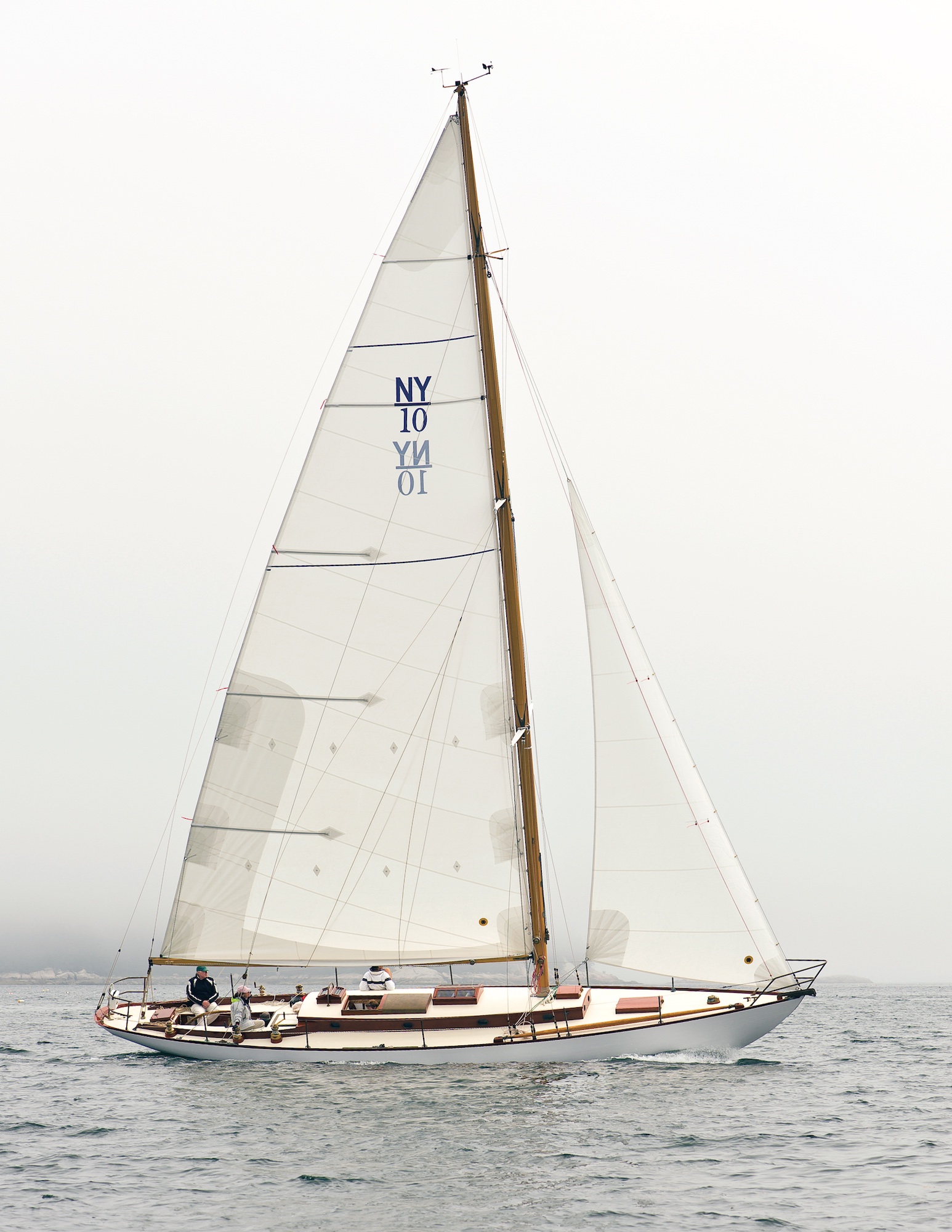
ISLA, New York 32 No.10 (of a total of 20), was thoroughly rebuilt last year by Buzzards Bay Yacht Services of Mattapoisett, Massachusetts. The job included a new mast, whose construction is detailed on the following pages.

When my company was hired to restore New York 32 No. 10, ISLA, in 2008, the boat had been out of service for over 25 years. The 20-boat New York 32 fleet was designed by Sparkman & Stephens in 1935 and built over the winter of 1935–36 by Henry B. Nevins of City Island, New York. When we found her, ISLA was a virtual time capsule, with an intact original interior and a complete set of original hardware. But the hull and deck were tired, to say the least, and the spars were beyond repair. So, included in the work list were a new mast and boom.

The New York 32 carries a hollow, oval mast measuring 63′ 5″. The owners were committed to maintaining ISLA’s originality, so we acquired the original spar drawings from the S&S plan collection at Mystic Seaport. These included ample detail: spreaders, tangs, boom, and masthead, along with the overall mast plan. The following steps describe how we turned those drawings into a new mast for ISLA.

Ordering and Preparing Lumber
ISLA’s mast is built of Sitka spruce, which has long been prized by sparmakers for its long, clear lengths, light weight, and impressive strength for that weight. From the plans we developed a lumber list for the mast, boom, and spreaders. While it is still possible to acquire excellent-quality Sitka spruce, it takes some searching and a keen eye for defects. We required at least 12/4 stock to fashion the forward and after staves.

For spars, it’s imperative that the wood be dry (below 15 percent moisture content) and free of defects. The grain must be vertical. Our first attempt to procure lumber for this mast resulted in us receiving a batch of 12/4 Sitka spruce that was case-hardened. It was dry to both the touch and to the moisture meter, but once milled and its center exposed, its moisture content went off the scale. When we tried to rip it on the tablesaw, it pinched the saw’s blade and stopped the saw. We replaced that batch of wood with properly dried material, and learned a lesson in the process.

We ran the rough-sawn boards we had purchased through the thickness planer to take “fur” off of each one, allowing for a better inspection of the surface of the wood. When doing so, we kept in mind the minimum thickness of the staves, so we wouldn’t carelessly plane off too much. With this done, we examined each board, measuring its usable portion, marking visible defects, and labeling each piece for its intended location in the mast. A board with tight grain is slightly denser and thus heavier than one with wider ring spacing; we strived to locate these heavier pieces toward the bottom of the spar. If another board had slight grain runout, we’d consider using it in the mast’s heel where it is under less stress and is backed by solid blocking.
It’s also important to keep in mind the locations of the scarfs when selecting the lengths of stock that will compose each stave, for the scarfs must be staggered.

Utilizing the Drawing

The drawing shown here is an illustration of the original Sparkman & Stephens mast plan for the New York 32, whose vertical scale was compressed in order to fit the mast’s dimensions onto a single sheet of paper. From the drawing we created a table of offsets for the mast. To do this we drew a series of stations, 5′ apart, perpendicular to the mast’s centerline. We did this for both the side and forward views of the mast.

The drawing shown here is an illustration of the original Sparkman & Stephens mast plan for the New York 32

For the forward and after staves, we recorded the overall thickness of the stave (that is, its thickness before hollowing) and its half width. For the side staves, we recorded the thickness and width at each station. We converted the mast plan drawing from 32nds of an inch to decimal units, which I find best when working to close tolerances using digital calipers. We then made up 10″ × 10″ lauan templates on which to draw the sectional shape of the mast at each station. Since the forward and after profiles are arcs of a circle, we transferred these shapes from the drawing to the lauan with the aid of a compass. After each shape was transferred we cut out these lauan templates with a bandsaw. On each template, we also recorded the sidewall thickness, forward and after wall thicknesses, and distance from the heel of the mast. Building this New York 32 mast as was done originally requires hollowing out the thick forward and after staves in order to lighten their weight. So, once again using the mast plan, we made templates for the mast’s inside shape at each section.

The Spar Bench

The first step in building the mast is to construct a spar bench. We wanted a sturdy bench that was straight and set at a good working height. Typically, a spar bench comprises a series of sturdy sawhorses spaced 5′ apart and fastened securely to the shop floor. Identical wooden sawhorses work well for this; once they were secured to the floor, a mason’s string was run to assure that the tops were all in the same plane; the tops were then shimmed as needed to achieve this. The 2 × 10 plank seen here being screwed to the sawhorses is to support the staves during the scarfing operation, and will later be removed.

Gluing Up Full-Length Staves

On our nice, solid bench, we laid out the wood for each of the mast’s four staves end-to-end and developed a final scarf plan. We planed the stock to the maximum designed thickness for the forward and after staves (2.875″) and for the side staves (1.25″). Then we scarfed the stock together to create the full-length staves. Careful layout and labeling were required for this step. We examined the stock and put the most visually pleasing sides facing out, and we spread out the scarf locations to avoid clustering them. Scarfs were cut to a slope of 12 to 1, with their lines drawn onto the edges of each piece. They were rough-cut on the bandsaw, and then finished with a jig and a router. With the scarfs cut, we assembled the pieces dry and ran a string down each of their centerlines to confirm that each of the four full-length staves, once glued, would be straight.

When we were certain that the staves would be straight and true, we screwed blocks to the spar bench to chock them in place. The individual pieces could then be removed from the bench, turned over for gluing, and placed back in their precise positions. The final step in preparing the scarf for epoxy glue was to rough up the surface of the glue joint. Eighty-grit sandpaper backed by a long block works well for this, as does the technique we used: a Japanese pull saw drawn across the grain so its teeth combed the surface. (This process is for epoxy gluing only; resorcinol and other glues rely on smooth mating surfaces.)

Once the surface was roughed up, we vacuumed both faces of the joint and then wiped them with a clean rag and denatured alcohol until the rags came up clean. We then wet out both gluing surfaces with straight epoxy and allowed that to stand for several minutes while it penetrated the wood. Dry spots were wetted a second time. We then applied epoxy thickened with colloidal silica to one face of the joint. Using large bar clamps and modest pressure, we clamped the joints, making sure we had a nice, even glue squeeze-out.

Tapering the Staves

Once the staves were glued full-length, we selected the aft stave, blocked it straight on the spar bench, and snapped a centerline. Then, using the information from the lauan templates and the offset table, the points representing the stave’s profile were laid out and connected with a long, limber batten. One of the side staves was marked similarly.

We rough-cut the profiles with a worm-drive circular saw being careful to leave the lines intact. We then cut closer with a power plane, and then shaved precisely to the lines with an appropriate hand plane, making sure that the edges stayed perfectly square. With one stave of each profile now complete, we used each as a template for its mirroring stave, making the final cuts with a router and bearing bit to complete the second pair of staves.

To minimize weight aloft, the wall thickness diminishes as we progress up the mast. Once again we turned to the lauan templates on
which we’d recorded the wall thickness at each station. Using digital calipers, we recorded on both edges of each stave the wall thickness at each station and connected the dots with our long batten.

This line, yet to be cut, is shown in the drawing. The stock was removed from the outside faces of the staves, the bulk of it with a power plane. The final cleanup was completed with a bench plane.

Rabbeting the Forward and After Staves

With all four staves milled to the correct taper and wall thickness, we rabbeted the edges of the forward and after staves. These rabbets helped immensely with alignment during glue-up. We cut them using a long batten and a router, with the depth of rabbet determined by the wall thickness of the side stave.

Hollowing the Forward and After Stave

The final step before gluing the staves together was to hollow out the forward and after staves. On the lauan templates we referred to the inside profile shapes we had recorded from the mast drawing. Dividing the inside profile into 1⁄4″ sections, we measured and recorded the depth at each section. We did this at each station. The inside face of the stave was thus lined off in 1⁄4″ increments.

Then, using a circular saw set at the depth indicated by the lauan template, we cut kerfs in the inside face of the stave. With each pass of the saw, we reduced the depth of the cut as we moved toward the masthead and farther from the center of the stave. With the kerfs completed, we used a gouge to scoop out the waste. We arrived at the final shape by using a backing-out plane followed by 80-grit sandpaper on a round sanding block.

With the staves cut to their profiles and tapered in thickness, and the forward and after staves rabbeted and hollowed, we double checked that the spar bench was still straight. The next step was to lay the after stave on the bench, sail-track side down, and hold it straight with blocks screwed to the bench so the spar could not move. We then did a final dry-fit of the three remaining staves to make sure all joints were tight.

Gluing

When satisfied with the bench and the joints, we began mixing glue. A large spar such as this takes about four people to glue up; any fewer, and panic would certainly ensue. The glue-up seems to work best as a two-step process. The first step was to glue the side staves to the after stave, using the forward stave as a dry-fitted guide to ensure that the side staves remained parallel. We clamped the spar in 1′ increments, checking that it remained square along its entire length. Using the two-step process allows ample time to fit and install the solid blocking at the head and heel of the mast. The drawing calls for blocking in the bottom 11′ of the spar and in the top 2′ 6″.

The blocking is solid until about the final foot, where it tapers to a feather edge on either side of the spar, forming a swallow-tail shape to avoid a hard spot. This heel blocking has a drain hole, in case of water intrusion. There is no blocking at the spreaders; instead, the spreaders have an external bracket and blocking system that transfers the load evenly to the spar.

We coated all interior surfaces with epoxy. At this stage, we also ran all of the wires inside the mast, securing them with large cable clamps. (Conduit fastened securely along the interior of the spar—and through the blocking—works well for this, too.) When everything was satisfactory inside the mast, the forward stave was glued to the side staves to cap the assembly. Several varieties of clamps can be used when gluing up a spar: spar clamps, bar clamps, C-clamps, or a banding tool. We used a combination of clamps and a banding tool supplemented with wedges to further tension the plastic band.

Shaping

With the glue cured and the clamps off, it was time to begin the shaping process. The first step was to plane off the excess glue. With that done, we again turned to our handy lauan templates and began the process of eight-siding the spar. Using the exterior cross-section drawn on each template, we found where a 45-degree line would be tangent to the mast’s outside surface at each station. We transferred these points to the spar, and with the long batten connected them with fair lines.

We then set our circular saw to 45 degrees and made a cut, just leaving the line. Repeating this on all four sides of the mast, and then fairing up the saw cuts with a power plane followed by a hand plane, yielded an eight-sided spar. We then lined the spar off again to 16 sides, but this time we omitted the circular saw and removed the waste with only a power plane. When we had the spar 16-sided, we finished the rounding and fairing with hand planes and a custom-built concave fairing board. Once again our lauan templates came into play, as we used them to confirm the correct shape at each station. Two other details that had to be considered at this stage were the shape of the heel of the spar, and the masthead detail.

This mast had to fit into a bronze shoe bolted to the maststep; we carefully shaped the heel for a snug fit. For the masthead, we departed from the original single heavy bronze halyard sheave that was mounted off to one side to allow for a two-part main halyard. In place of this, we used two smaller sheaves one for the halyard’s entry, the other for its exit—mounted in a custom made bronze sheave box. This saved quite a bit of weight aloft, and still allowed for a two-part halyard.

With the mast now shaped and sanded, we broke out the varnish and applied 10 coats before installing the track and hardware. We were fortunate to have all of the original tangs and other fittings for this spar, because fabricating them would have required quite a bit more work. With the spar varnished the hardware was installed, carefully bedded in soft compound. We were very careful in fastening into the Sitka spruce, as it is quite soft. We chose machine screws rather than wood screws for mounting the winches and the boom gooseneck track—after testing these fastenings on offcuts to find the best pilot-hole diameters.

This article was originally published in WoodenBoat No. 214, May/June 2010.