
 Harry Bryan
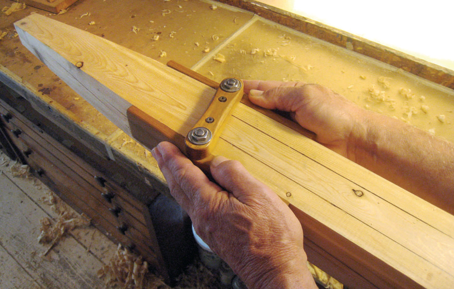
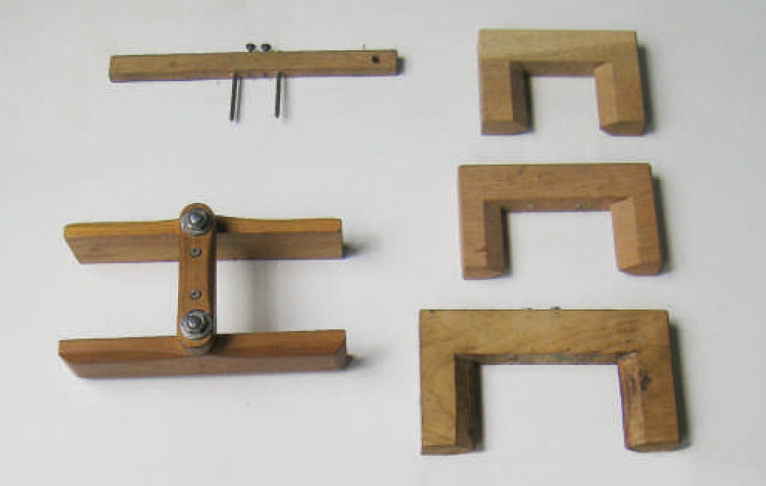
The author’s spar gauge, based on a type long in use at Mystic Seaport Museum, makes accurate marks for eight-siding a spar. This type of gauge is more complicated to build than others but easier to use, scribes lines all the way to the end of a spar, and works with spars of a comparatively wide variety of diameters.
Few articles written about making a boat’s spars fail to include instructions for building a gauge for creating accurate facets as an intermediate step between squaring and rounding. Usually called a spar gauge or an eight-siding gauge, this valuable tool can be used to help shape a mast, boom, gaff, oar, boathook, or any other round-sectioned shaft. Its particular forté is its ability to take into account the spar’s taper, making accurate guidelines that would be much more time-consuming with any other method of marking.
The important word here is accuracy. Any measuring or guiding tool should be made as accurately as possible, otherwise its errors will be reproduced (or at least will have to be accounted for) each time it is used. This article shows how to avoid potential sources of error and presents three different configurations of the gauge itself.
A common mistake while learning to shape spars is to do any rounding of the stock before as many accurate facets as possible are made. You will start with a tapered, four-sided spar that is square in cross-section. A spar gauge will be used to mark lines to guide the next step, which is to shape the spar to octagonal, and the lines will be accurate at any point along the spar’s length.
With a spar 3″ or less in diameter, 16-siding can be achieved with sufficient accuracy by eye, but spars larger than this will benefit from correctly scribed lines for 16-siding, followed by 32-siding and even 64-siding by eye. Accurate scribing for 64-siding is an unrealistic goal but the longer you resist reaching for the sandpaper, the easier sanding will be and the closer to perfectly round the finished spar will be.
 Harry Bryan
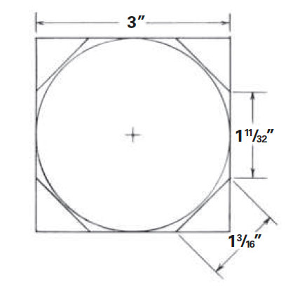
The geometry of an octagon shows the relative spacing of scribe lines for eight-siding a spar.
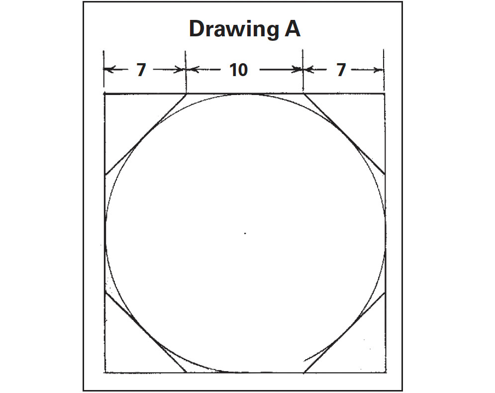
Drawing A shows the geometry for eight-siding, with a circle that represents the final shape of a spar at the point of its greatest diameter, drawn within the square section of wood from which it will be shaped. Also shown is the octagonal shape that will be the first step in rounding that spar. Two of the eight corners of the octagon lie on each of the four sides of the square. It is these points that the spar gauge will mark, in continuous lines along the spar’s length. Their spacing is in a ratio of 7–10–7 (actually 7–9.899–7).
However, this bit of math is not necessary to construct a spar gauge. The tools needed are a sharp pencil; a combination square; and, for 16-siding, a protractor and bevel gauge.
Presented below are three variations on making spar gauges. The first two styles are the most common. They are easy to make; nevertheless, accuracy should be a prime concern. The third design is more difficult to construct, but it has significant advantages.
In use, each gauge is placed over the spar and rotated until its guides contact the spar’s squared-off faces. The gauge is dragged along the length of the spar, with the guides kept in contact with the sides.
Spar Gauge Variations
 Harry Bryan
For small-diameter spars, a simple gauge works well. This one is intended for a 1 1⁄4″-diameter workpiece.
Gauge No. 1
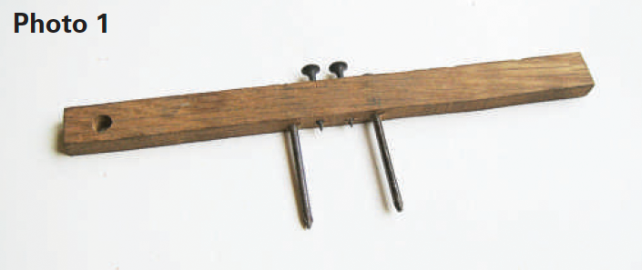
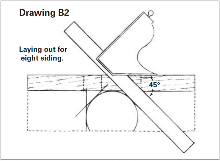
The gauge shown in photo 1 and in drawings B1 and B2 is perhaps the type most frequently used by builders of small boats. In common with each of the designs presented here, it has guides that slide along the outside faces of the spar.
In this design, the guides consist of common nails simply driven through holes bored in the cross-piece. (Large-diameter nails or dowels introduce inaccuracies to spar gauges, as described in Inaccuracies in Spar Gauges below.) This style is best kept small and used for spars 3″ or less in diameter.
 Harry Bryan
Using simple tools, the geometry of the gauge can be laid out on a hardwood scrap. Making the compass-scribed circle slightly larger than the actual spar will allow the guides to slip easily over the spar when scribing.
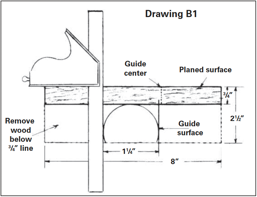
To make a gauge for a maximum spar diameter of 1¼”, first find a scrap of hardwood like the one shown in drawing B1, which is about ½” × 2½” × 8″. The exact dimensions are not critical, but the thickness must be uniform. Plane one edge straight. Use a combination square to draw a line parallel to, and ¾” from, this edge. The gauge, when finished, will use only this ¾” strip, but keeping the piece intact will simplify laying out the guides and scribing points, after which the excess wood will be cut away.
Next, midway along the length of this piece, draw a circle about 1⁄16″ to 1⁄8″ larger in diameter than the spar will be. This extra diameter assures that the gauge will slip easily around the spar and will not bind in use. This circle will be below and tangent to the ¾” line, as shown.
With the combination square registering on the planed edge of the wood, draw two 90-degree lines tangent to the left and right extremities of the circle and intersecting the ¾” line, as shown. These lines represent what will be the inside surfaces of the guide pins. A 2″ common nail would be an appropriate size for this gauge, so measure half the diameter of the chosen nail and carefully mark a reference line parallel to the line marked earlier. This new line corresponds to the center of the pin.
 Harry Bryan
A combination square’s 45-degree angle, held tangent to the circle, shows where the scribe points must be centered.
Next, hold the combination square’s 45-degree side to the planed edge so that the ruler is tangent to the circle, as shown in drawing B2. The point where the ruler intersects the ¾” line will correspond to the centerlines of the screws to be inserted for eight-sided scribing.
To complete the gauge, cut away all wood below the ¾” gauged line. Transfer the guide and scribe marks square across the lower edge of the remaining stick, and at its exact center use a drill press to accurately bore pilot holes of appropriate sizes for the guide nails and the scribing screws.
 Harry Bryan
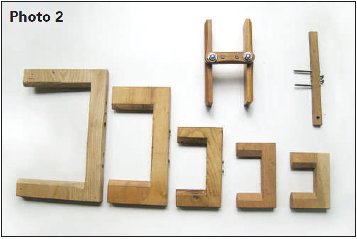
Spar gauges with shaped wooden guides, as shown at the bottom of the photo, are simple to make in a selection of sizes to suit spars of various diameters.
Gauge No. 2
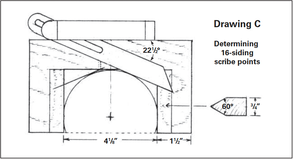
Laying out this gauge, shown in drawing C and in several sizes at the bottom of photo 2, uses the same principles as the first gauge shown. The dimensions given are for a maximum 4″-diameter spar. However, this style is appropriate for any size spar.
Instead of the guide nails used in No. 1, the guides for this style are cut from the block of wood from which the gauge is made. Bevel the edges of these guides, which will contact the sides of the spar, to approximately 60 degrees. The resulting edge should be nearly sharp and exactly centered on the wood’s thickness.
 Harry Bryan
For a 4″-diameter spar, this gauge is made with a 4 1⁄8″-wide throat. Here, the layout for 16-siding scribes is shown, with the bevel gauge set to 22 1⁄2 degrees and held tangent to the circle. Scribing screws can be set for both eight-siding and 16-siding in the same gauge, with the unused pair of screws backed out.
The method for laying out the eight-siding screw locations is the same as shown in No. 1. But this 4″ gauge will benefit from a second set of scribing points as an aid in 16-siding, and the method for determining those scribe locations is shown in drawing C.
Use a protractor to set an adjustable bevel to 22½ degrees. Then, as was done for the eight-siding points, draw lines tangent to the circle and carefully position two more screws. Screws especially show their usefulness as scribes here, because they can be easily withdrawn: first withdraw the 16-siding screws and set the eight-siding ones, and after planing the spar to eight-sided, withdraw the points of the eight-siding screws into the body of the gauge and set the other two for 16-siding. This is useful for all but the smallest spar gauges.
 Harry Bryan
Although more complicated to make than other types, an articulated spar gauge, based on one used by shipwrights at Mystic Seaport Museum, suits spars of a fairly wide variety of diameters.
Gauge No. 3
In “Currents” in WoodenBoat No. 176, Mystic Seaport Museum shipwright Walt Ansel described an articulated spar gauge donated to the museum many years ago.
In his words, “Not only do I covet this tool, but six other shipwright-boatbuilder types do as well.”
With such praise, I was drawn to construct one for myself. I have used mine for years now and can report that although you can probably get through life without one, it is indeed a superior tool. Its large side cheeks slide along the spar so smoothly that compared with the perfectly adequate styles presented above, it is like driving on a newly paved highway after miles on a rough dirt road.
The superiority of this tool is due to its large articulated side cheeks. Unlike the point contact made by the guides of other spar gauges, this one allows firm pressure against the spar’s sides with minimal drag. This design also eliminates the error described in Inaccuracies in Spar Gauges due to the gauge being too large for the intended spar.
For those who enjoy the challenge of creating a well-made tool, this one is worth the effort. The one shown in photo 3 and also visible in use in the lead photo on page 80 is detailed in drawings D1 and D2. It will scribe eight-siding guidelines for any spar 3″ or less in diameter. If a larger gauge is needed, the concepts shown here can be expanded for the required diameter, and scribing screws for 16-siding can be added, as described in No. 2.
 Harry Bryan
The plan for the cheek pieces is straightforward, but beveling the edges of the outside surfaces, as shown in the lower drawing, will make the tool more comfortable to use.The plan for the cheek pieces is straightforward, but beveling the edges of the outside surfaces, as shown in the lower drawing, will make the tool more comfortable to use.
Use a dense hardwood for all of the tool’s wooden parts. While the inside surfaces of the cheeks, as shown in drawing D1, should be left plain and flat, the outside surface bevels will dress up the look of the tool and, more important, will add comfort in its use.
The mortise for the pivot bolts cut into the inside surfaces is best made by clamping both cheeks together. Using a drill press and brad-point drill bit, bore a 3⁄8″ hole to a depth of 1″. The point of the drill will follow the seam between the two pieces, assuring an accurate half-hole in each piece.
 Harry Bryan
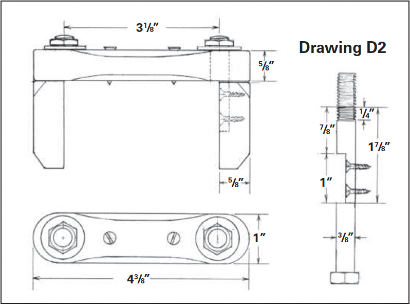
As shown in the right-hand drawing, the threaded end of the bolt is cut to leave 1⁄4” of the threads. The shank is cut to length, the the lower 1” of its length is cut in half longitudinally so that it fits flush in the recess bored in the cheek pieces, as shown in the upper left view.
As shown in drawing D2, the wooden connecting link carrying the scribing pins will have its pivot bolt centers laid out 3 1⁄8″ apart. This will also make the maximum distance between the cheeks 3 1⁄8″ to give clearance for use on up to a 3″ spar. Calculate the centers for the scribing pins using the graphic method shown for eight-siding scribes for gauge No. 1 and 16-siding scribes for gauge No. 2 above.
Bore 3⁄8″-diameter holes for the pivot bolts and drill pilot holes for the No. 6 × ¾” screws to be used for scribing pins. Take care that the holes for the pivot bolts are a close fit with the bolts being used. The pivot bolts are made from 3⁄8″-diameter, full-bodied bolts at least 3″ long. Full-bodied means that the unthreaded part of the bolt is an accurate 3⁄8″.
Cut away the extra length of shank and extra threads using the dimensions shown. With a hacksaw, cut the lower 1″ of the pivot bolt in half lengthwise. Finish with a file. Drill and countersink this half-section for the No. 6 × ½” flat-head wood screws that will hold each bolt to its cheek piece.
Create two nuts by sawing a standard nut in half. These low-profile nuts are appropriate for the look of the tool. When tightened against the end of the bolt threads, the tool should articulate freely yet not have excessive slop. This is easiest to achieve by inserting the bolt with a tightened nut and washer through the connecting link and holding this assembly against the side-cheek mortise to mark the lower end of the bolt before cutting its final length.
 Harry Bryan
Guides made with too-large pins or a span too large for a given spar can cause inaccuracies in spar scribing. Keeping the pins to minimum diameters (upper left) or making fairly sharp sides (right) minimizes the issues, but the articulated gauge (lower left) largely eliminates them.
Inaccuracies in Spar Gauges
Inaccuracies can be introduced into the use of spar gauges in several ways, all of which can be traced to the way the gauges are made or how well they fit the size of the spars they’re intended for.
It is common, for example, to see large-diameter dowels used as guide pins. Dowels and any other round guides will cause inaccuracies. This problem is proportional to the diameter of the guide and to the amount that the gauge must be rotated for its guides to make contact with the spar.
The drawing below shows the layout for a 3″-diameter spar and a gauge using ½” dowels as guides. In this case, the distance between the guides is 4½”. This combination requires that the gauge be rotated significantly for the pins to make contact. As shown, the pins do not contact the spar at their intended point.
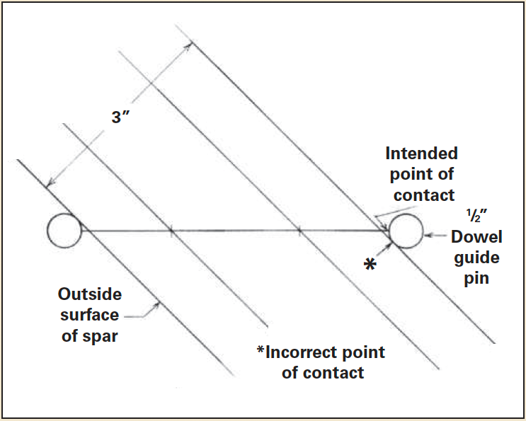 Harry Bryan
Accurate scribing leads to accurate planing. Too-large guides or too-wide gauges can cause errors, which worsen as the angle of the tool increases as a spar tapers.
The introduced error causes adjacent facets of the octagon to be more than 1⁄8″ different in width, as shown in the drawing at right below. A gauge made like No. 1 in the main article uses nails as thin guides to minimize this error; gauge No. 2 in the main article has nearly sharp points of contact to eliminate it, so long as the gauge doesn’t have to be rotated too much.
Another common problem is using a gauge too big for the spar being made. As the spar tapers, an increasing twist in the gauge is necessary to maintain the contact of the guides. An excessively large gauge for the size of the spar will need an excessive twist, increasing the error of large-diameter guide pins.
 Harry Bryan
A spar gauge with large-diameter pins or one too wide for the spar can cause inaccuracies, which show up in unequal widths of the facets, throwing off accurate eight-sided planing.
Even No. 2, with a nearly sharp 60-degree edge, can only be twisted 60 degrees before its guide points no longer touch the spar. These errors will be reduced, or eliminated, if the distance between the guides is only slightly larger than the largest section of the spar.
The problem can still occur, however, in areas of comparatively extreme taper. Because the gauge will always be twisted with respect to the spar’s centerline, and because the spar has a great amount of taper, the leading guide will be “reading” a different diameter than the trailing guide. This error is so small for most of a typical spar’s length that it can be ignored. However, on many small-boat masts the diameter decreases quickly between the partners and the mast heel.
 Harry Bryan
Heavily tapered spar heels can throw off scribing, with the “leading” and “trailing” points marking lines that must be averaged. An articulated gauge, such as No. 3 in the article, avoids the problem.
If, after scribing the lines for eight-siding in this area, another pass is made so that the opposite guide pin is in the lead, two diverging lines will be made, as shown above. (The problem is worse if the gauge is already too large for the spar being scribed.) The correct guideline will need to be drawn halfway between these two lines.
Using pencils instead of screws as scribing points also causes problems. Pencils are almost always shown as the marking medium for spar gauges, and if they are accurately installed they do not cause errors. However, they are usually the weakest link in an otherwise rugged tool. It is difficult to keep two pencils marking effectively at the same time while remembering to keep the guides in contact with the spar’s sides. Inevitably, a rough spot in the wood grain will break one of the pencil points. Pencils also require a precise fit so that they can be adjusted easily yet not slip in use.
Brooklin, Maine, boatbuilder Eric Dow advises using only one pencil and making two passes down the spar to maintain a better feel for the work and to make the point last longer.
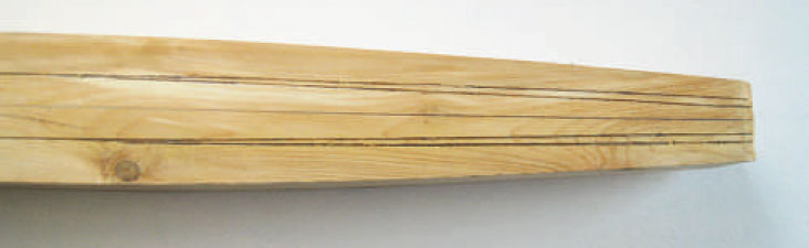
For me, the answer to broken or loose pencils is to use wood screws as scribes instead. They are always sharp and will stand up to the abuse of heavy pressure or small knots. Their depth of cut is easily adjustable, and they can be set so that just enough of the point is exposed to clearly mark the lines while at the same time the body of the gauge itself acts as a positive stop for that depth.
Also, the slight grooves made by the points will be exposed with the last plane shavings finishing each facet, giving an accurate visual check to your work. The grooves, which can be darkened with a pencil if needed, will be removed during 16-siding.
Contributing editor Harry Bryan lives and works off the grid in Letete, New Brunswick. For more information, contact Bryan Boatbuilding, 329 Mascarene Rd., Letete, NB, E5C 2P6, Canada; 506–755–2486.