Keel and Sternpost
Your designer probably calls for a white oak keel, properly air dried. This is good; he could have been much more specific, and gotten us all in trouble. He might have inherited from his Naval Construction days one of those little electric moisture-content indicators, and gotten all excited about what it told him. (Although, confidentially, I’ve watched him read the shielded dial, nod with satisfaction, and mark “OK” on a timber that had been swaying to the summer breezes three weeks before.) He might even have been able to recognize white oak when he saw it, although this is unlikely. But he has fulfilled his duty by the book, and said, “white oak, properly air dried.” We can take it from there.
Good timber
The keel for the boat in our example will spend most of its life in the water, and will never, except by awful accident, lose much of its moisture. It should therefore be at its maximum size when fitted to the ballast casting (lest, if dry, it swell its normal 5 percent, hang out over the metal, and strain the floor-timberfastenings), and should be kept at that size, throughout the building process, by liberal doses of sealer. I favor a mixture of linseed oil and kerosene, with a slug of Cuprinol for luck. If the wood will take a pencil mark, it’s dry enough. If it’s too wet for that, use a rase knife, which marks the wood by scoring it.

And if you can’t get white oak, the wood most favored by designers and builders, what then? Long leaf hard pine, if dense and heavy, is as good in almost every respect, and somewhat better for a boat that’s going into southern waters. “Spar-quality” Douglas-fir (which becomes “Oregon pine” on its way to the boatyard) is magnificent timber, good enough for any part of a boat except bent frames and fancy trim. If you were in England you’d sigh with ecstasy over a bit of American elm, which we use for flooring horse stalls. And then there are other varieties of oak, which we won’t mention by name, but which get whiter and whiter as they travel from the mill to the shop. I could bear the thought of teak, if someone gave me a piece. If I were in Norway, or Australia, I’d ask a local builder what he’d use in his own boat and do likewise.
A flat keel such as this one-5 inches deep and l4 inches wide at mid-length-should come out of the log entirely clear of the heart, and lie small-face down. This gets you away from possible cup shake, porous pith, and the tendency to check open at the ends, where stem and stern post must attach with absolute integrity. Figure 4-l shows the “Hitch” cuts that yield the best timber for the keel. Obviously, the tree that produces this off-the-side timber will be much bigger than you’d need if you were satisfied to take a boxed-heart keel. (Just as obviously, there will be a twin on the other side, which gives you a choice, and the problem of what to do with the second keel. If you share my passion for good timber, you’ll buy it, along with all the other full-length pieces out of that log. You never know when you might want to build another boat-and clear toerail stock 22 feet long is hard to find on short notice.)
Marking method
Let’s mark this keel and cut it to shape, before we take up the various problems and possible alternatives in the other pieces of the backbone.
I assume that the ballast casting has arrived, or has been revealed behind the bathtub, and that you have it lying comfortably on its side, on 8-inch blocking, with the plane of the top face clear of obstructions, and room to get a long auger through the core holes from the bottom. (I am assuming, furthermore, that you and I are talking about the full-length casting as shown for our example; or that you have, while my back was turned, fitted deadwood to a scarfed casting to achieve the same full-length, under-the-keel, flat-on-top shape, all the way back to the rudder stock. I’ll have something to say about this later, in defiance of strict chronology.)
What you are after right now is the exact shape of the top of that casting, with bolt locations marked on the bottom of the wood keel, so that you can make the proper allowances (for widening to the rabbet width, because of the flare of the wineglass sections) and cut it precisely to shape.
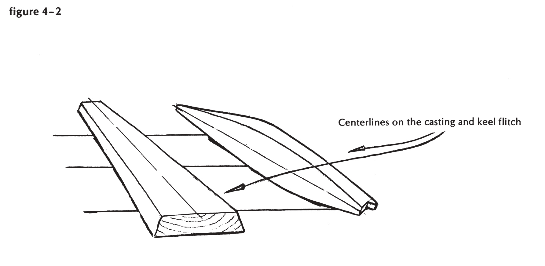
Mark a centerline on the top of the casting from center to center of the two ends, of course-as shown in Figure 4-2. If the top of the casting shows a slight discrepancy in width on either side of this line or through the middle, ignore it, and don’t tell the owner. It’s too late for tears, and the lack of perfect symmetry won’t do any harm. (We always judged the timbre of an owner by the way he phrased the inevitable question at the end of his first season. It might be “Why does she sail even better on the starboard tack?”, but it was more likely to come out “Why the —- is this thing slower with the wind on the left-hand side?” We never came up with a really good answer, but we propounded some wonderful theories concerning the strange behavior of sails, and the clockwise rotation of objects in the Northern Hemisphere.)
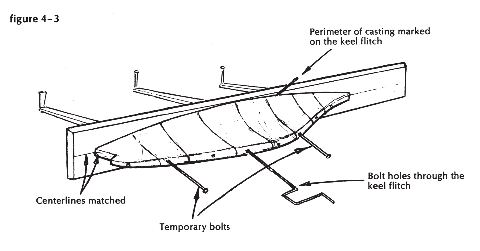
Now mark, with great care and consideration, a centerline on the lower face of the wood keel. Get from the loft floor the “expanded” locations of the stations, and square them across on this lower face. Gather rollers, peaveys, a toe jack, wedges, bar clamps, and friends, and get the wood against the ballast, solidly, with centerlines matching, and precisely located fore and aft. Think hard, and then bore two bolt holes, one at each end of the casting by way of core holes, through the wood keel, as shown in Figure 4-3. If the casting was cored with I-inch pipe, it’s likely that your 7/s-inch auger is the tool to use, unless you’ve done a painful lot of reaming. Make up two temporary ½-inch bolts, and set them up through keel and casting. Now you know that nothing will shift, and you can proceed to mark the outline of the casting on the wood, and bore the other bolt holes. Measure for the lengths of all keelbolts (bearing in mind, and allowing for, the extra lengths needed at the after and forward ends, where they must reach through the stern knee and forefoot, respectively), and order them now, if they are to be made of galvanized steel. Take out the temporary bolts, lay the timber bottom-up, and mark for the outline cut, which will be exactly in the vertical plane of the rabbet line. Perhaps we should rephrase that, and get the horse in front of the cart where he belongs: The flaring sides of the casting, if continued smoothly upward to the height of the rabbet as shown in the body plan, will dictate the width from the centerline to the rabbet at each station throughout the length of the keel. Join these points with a fair curve, and you are ready to cut. If the rabbet width does not agree exactly at all points with the widths originally laid down, don’t worry too much about it. Later on, you can alter the lower ends of the molds, within reasonable limits, to allow for this shrinking or swelling of the casting.

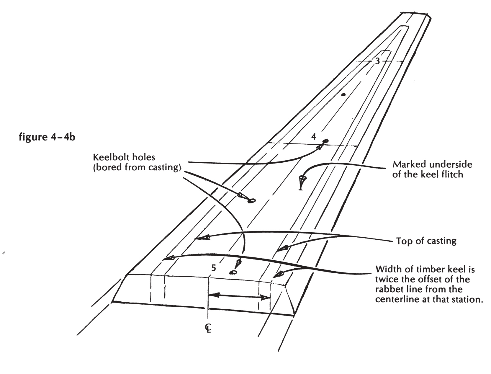
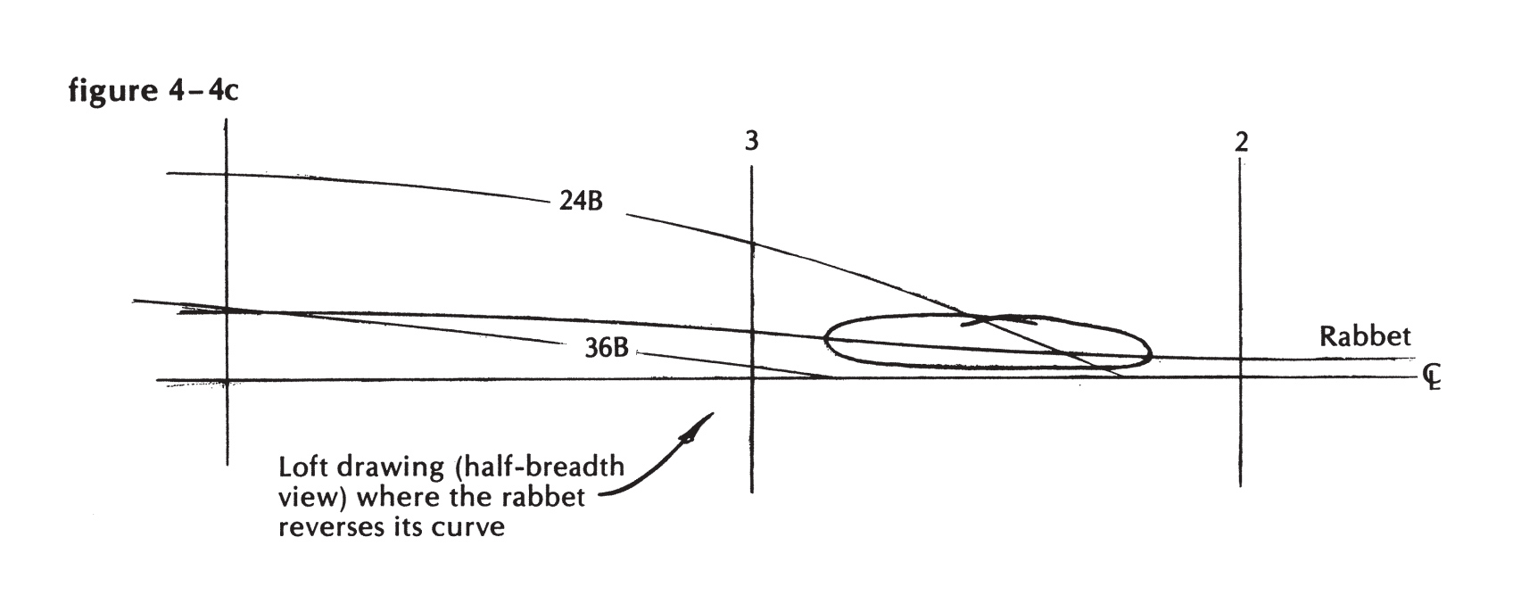
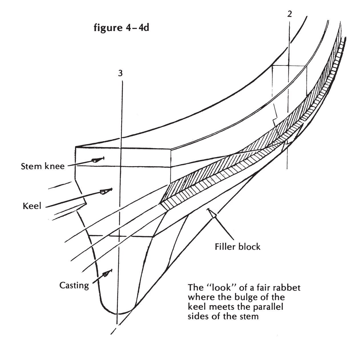
Now, the bottom face has been marked to match the top of the casting; bolt holes have been bored; and the corrected line ( to the width of the rabbet) has been drawn in way of the casting, and continued forward to join with and fair into the rabbet as marked on the stem (Figures 4-4a, 4-4b). You will have noticed, long ago, when laying out this half-breadth of rabbet on the floor, the slight reverse in its curve just before it reaches the stem (Figure 4-4c), and the manner in which it straightens out and follows the parallel sides of the stem thereafter (Figure 4-4d). Pardon me if I seem to doubt your aptitude in the spatial relationships test. I know of three designs, one of them widely_ built to, all of them done by designers who should have known better, and all of which contain this glaring fault-the assumption that the rabbet line can show an abrupt change in direction as it leaves a swelled keel and encounters a parallel-sided stem. I built one of these boats, when I was very young, and it was a painful and costly experience. I hadn’t then learned to think like a gar board ( that has an unflattering connotation) or to look for possible errors in every set of plans that came along. I finally got smart; and you are expected to become so, now that I’ve told you how.

The keel is cut
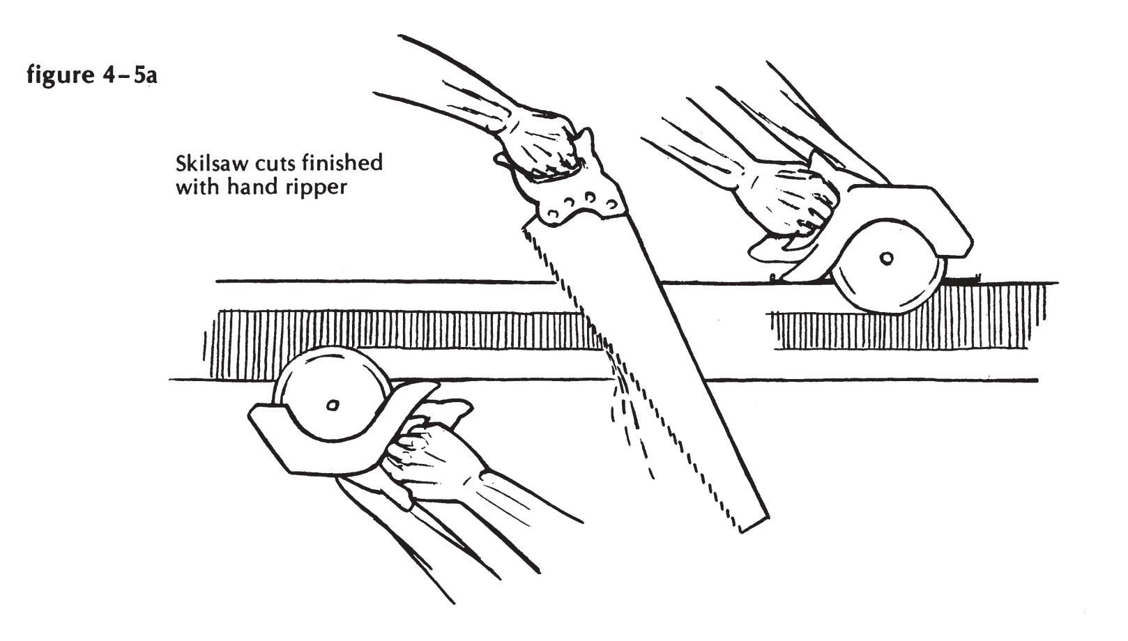
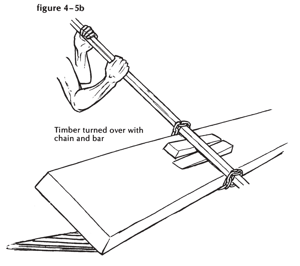
So we have a fair line to cut to, but a thick timber to cut through. Take your portable electric saw, with its sharp, well-set 8-inch blade at full cutting depth (23/4 inches, that is) and check to see that the blade stands precisely square to the shoe. Try a practice run, around a similar curve, to learn the proper allowance to make from the guide mark on the front of the shoe. You’ll want to leave the mark, but just barely. Cut with the wide part of the shoe inside. Don’t push too hard; have a small assistant sweeping and blowing ahead of the cut. When you’ve gone the length, both sides, get out your extra-long 5/32-inch drill, and shoot holes down through the saw kerf and out the other side-one at every station, one or two between, 1 foot apart at the forward end, where the reverse comes. Turn the timber over. (If you can’t do this with a peavey, chain a 6-foot bar to it, as shown in Figure 4-5b. Take the slack out of the chain by driving wedges under it.) Stand tenpenny nails m the postholes you just punched through, spring a batten to them, and mark for the cut. Your saw should follow the bottom kerf with no more than 1/s-inch error either side. (And what if the keel is 6 inches thick, and the saw cuts don’t meet? Pray that they line up, and finish the job with your handsaw.)
Set your locking bevel to the angle between the perpendicular station ordinates and the top of the keel, on the laid-down profile, and transfer the station marks up the sides and across the top of the keel. Run a true centerline along the length of it, using string, a straightedge, and a rase knife, so that you’ll be able to find the line through the sawdust and sealer. Look to the profile, and score the rabbet line (Figure 4-5c), but stop short of the forward end until the stem (whose lower-end rabbet is also left unfinished) is in place, and you can flow a true curve through the intersection. Leave this now and consider the remaining members of the backbone-stem, sternpost and its knee, and the tail feather.

And now, the stern post

The sternpost, like the keel (and for the same reason), should be cut from a timber that is not thoroughly seasoned. The perfect cut, as shown in Figure 4-6, would have through its middle a radius from the center of the log, with the growth rings crossing it almost at right angles-“rift sawn,” or “edge grain,” in the purest sense-dear of the heart on one edge, and stopping inside the sapwood on the other. It is unlikely that you would find an oak butt big enough to provide this ideal sternpost, which must come from rather less than the half-diameter of the log. The next best choice is a flitch like the keel, off the side of the log, well clear of the heart. I would avoid a boxed-heart timber if possible.
The problem of transferring a rabbet line from a pattern is solved thus: Drill small holes clear through the pattern at 6-inch intervals along the penciled rabbet line; prick the timber through these holes in the pattern while it is in place, for marking the outline. Saw the timber to shape, plane all faces square and exactly to the marks, then place the pattern on the reverse side, and prick through the same holes (Figure 4-7). You will, of course, use a batten to draw a curve through all these pricked spots on both sides to guide later on in cutting the rabbet. (The casual “saw-to-shape” above will have been done with the 8-inch portable saw, just as you did when you cut the keel. One cut in the propeller aperture is inaccessible to this treatment, however, and you’ll need to make this one with a series of overlapping auger holes, square through, just clear of the line. Clean off the rough points with an adze and a plane.)

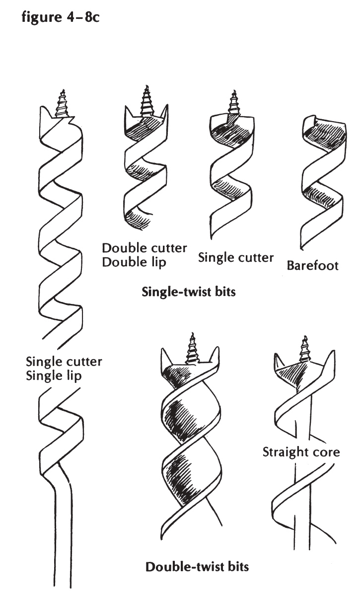
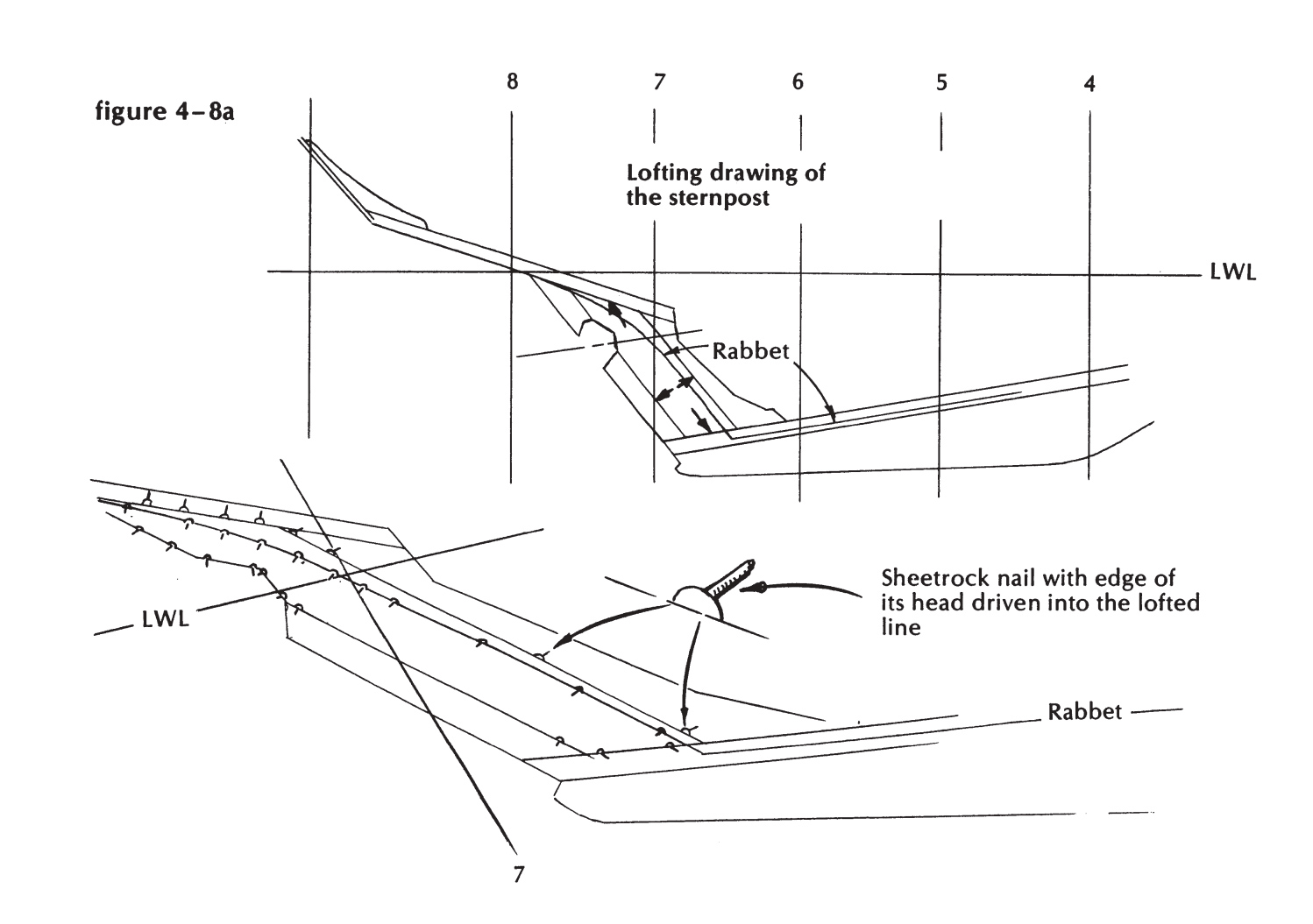
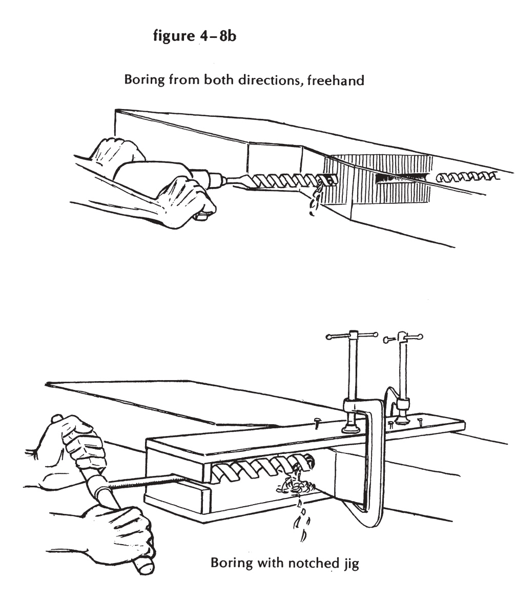
Let’s bore the shaft alley before we go on to making the stem. You will have transferred, from the stern post pattern, the line of the shaft in profile-marked on both faces of the timber and squared across its forward and after edges (see Figure 4-8a). The shaft line terminates on the aft face of the sternpost in way of the propeller aperture, where you can prick-mark its exact center, and start a hole for it with your expansive bit. At this point I usually get impatient, clamp the timber where I can aim along the line comfortably, and proceed to bore halfway through it, freehand, with a barefoot auger (if I happen at the moment to have an electric drill with enough torque to handle it). Then I flip the timber over, cut enough of a flat (with gouge and chisel) to start a hole on the forward face, and bore back through the tunnel. This is a bare 15 inches of hole, and no great feat. You may feel better boring more slowly by hand with an auger whose shank is running in a notched guide, precisely located by a straightedge, in line with the desired shaft hole (Figure 4-8b ). With such a guide, you should be able to bore true, all the way through from the aft to the forward face, in one operation. Turn the boring tool with a 3-foot cross handle, or a 30-inch pipe wrench. But if you are using a worm auger (which has a lead screw) instead of a barefoot one, beware: it will crawl to the starboard every time. (Figure 4-8c depicts the variety of drill bits available to the boatbuilder.)
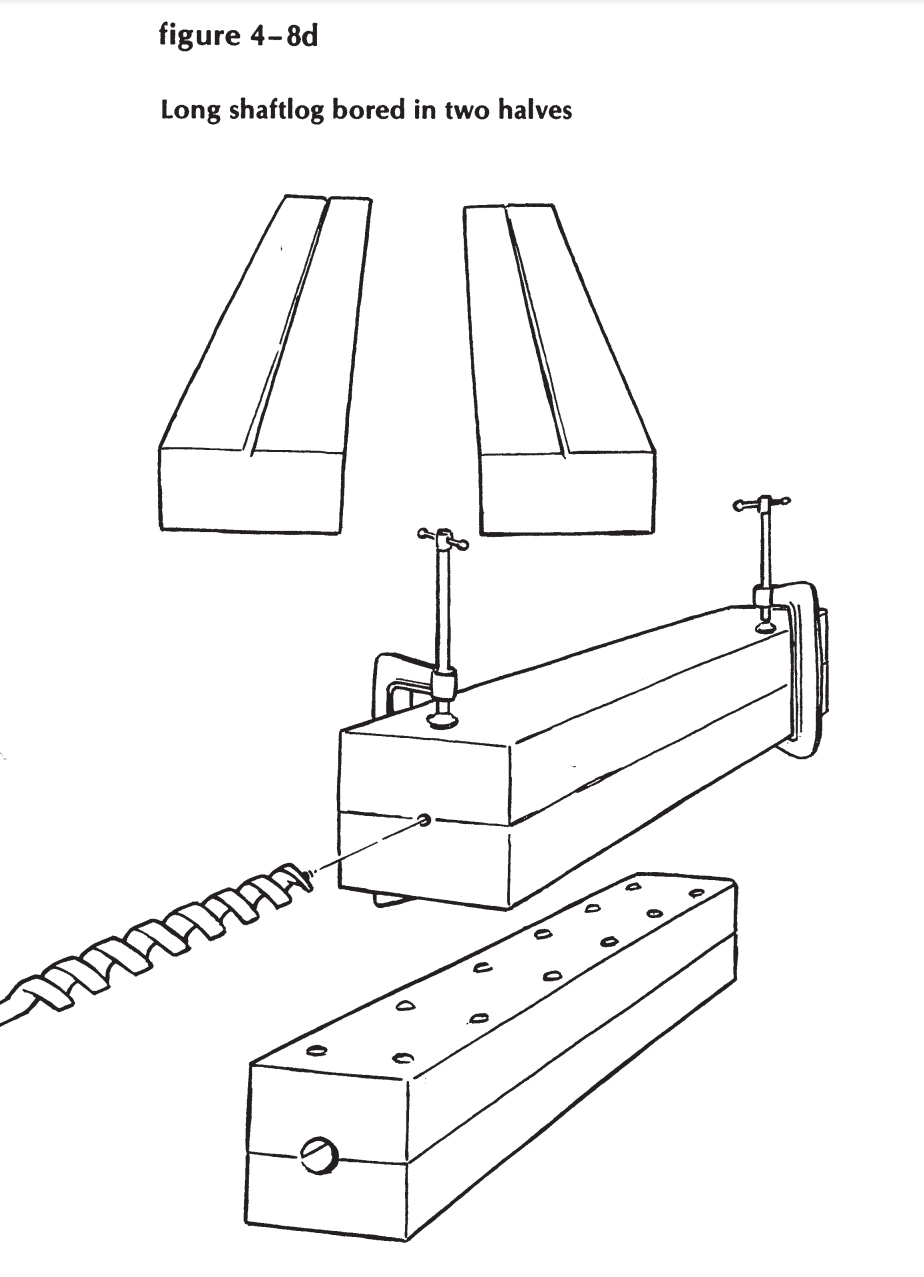
While we’re on this subject, let me tell you the only easy way to make a long shaftlog, bored exactly on center from end to end. Plan the log in two halves, one above and one below the centerline of the shaft. Score both halves, dead center, full length, on their contact faces (Figure 4-8d). Clamp them very firmly together, groove to groove, and follow the groove from end to end with the worm of a ship auger. Don’t worry about splines, feathers, glue, or outing flannel when you join these together. Oak casks don’t leak; neither will these, if you put enough bolts through them.