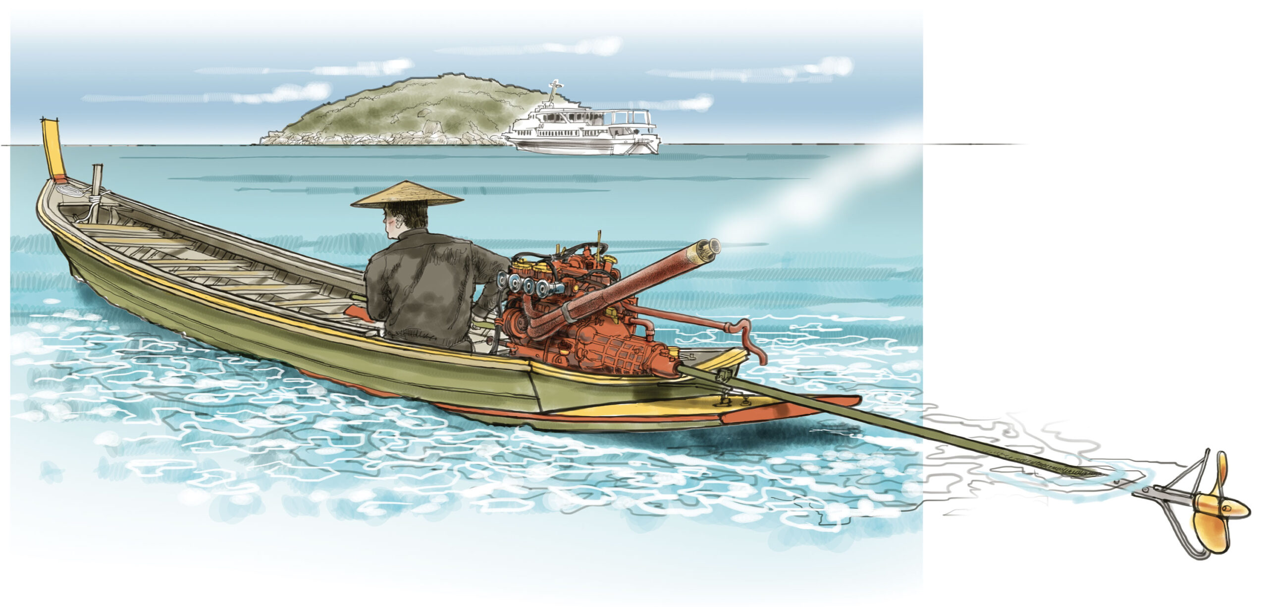
When boats began using internal combustion engines at the turn of the last century, we began to put holes in hulls. Today, an inboard-powered motorboat or a sailboat with an auxiliary engine must be engineered to keep a dry inner hull while sending power to the wet outside—right through the hull. Vibration, wear, torque, and corrosion conspire to break the best mechanical schemes that separate engine power from the water.
Your boat’s ability to project power from a dry motor to a wet outside depends on an interlocking set of systems that begins at the fuel filler cap and ends in the wake of your boat. Here, we’ll introduce the parts of the drivetrain—the system that begin where the engine ends— and we’ll also examine some important supporting systems (fuel, and the combined exhaust and cooling systems) that also require holes in the hull.
One rough but resourceful solution to the problem of transmitting power without compromising the hull is the Southeast Asian “longtail” drive shown in the illustration above. It’s an engine—whatever’s available, apparently—mounted on an improvised pivot at the wide, load-carrying stern of a shallow-draft native craft. The long driveshaft, sometimes stiffened by an exterior shaft rigged with spreaders and shrouds, turns a large propeller with a protective bent skeg. These thin-water skimmers howl along canals and rivers into surprisingly shallow stretches and even up onto the beach. They would probably not be USCG approved.
Drive Geometry: Variations on the Theme
Engine propulsion can be transmitted from the engine to the propeller in one of several basic formats.

Outboard Motor in a Well
Some workboats and fishing boats have an outboard motor hidden in a well, rather than hanging on the transom. This places the outboard’s propeller closer to the turning pivot of the hull and farther from loose lines and obstructions. Many sailboats and pleasure boats tuck an outboard motor in a covered well aft so the motor noise is reduced, fittings and fuel lines are out of the way, and a more traditional look is preserved.
Inboard Driveshaft through a Skeg
This configuration is the common and robust solution to inboard power. It demands a well-aligned, well-sealed driveshaft to prevent leaking.
Saildrive
This vertical-shaft assembly is for fin-keeled sailboats; it’s compact and effective with its weight balanced toward amidships
Inboard V-Drive
This space-saving configuration is employed when interior layout limits the engine placement forward, or hull shape denies shallow shaft angle.
Inboard/Outboard Sterndrive
In this scenario, an inboard engine powers an articulating outboard-style propeller assembly through the transom.
It offers the power and inboard balance of an inboard motor with the directional thrust (and, hence, nimble steering) of an outboard.
Jet Drive
Once an exotic device, the jet drive is now commonplace. It ducts water through an impeller to exit at great force through a nozzle. It’s most common in PWCs (personal watercraft, or jet skis) but it’s also found in larger boats. Some resourceful builders have torn the guts out of PWCs and placed them in more traditional designs.
Anatomy of an Inboard Installation
A classic runabout’s drivetrain is laid out with attention to lubrication, corrosion, watertightness, and vibration damping. Critical parts of the system are:
A. Propeller
Matching a propeller to your engine and boat requires some careful calculation—as well as some trial and error. Propellers are a book-length topic, and the best book on the subject is The Propeller Handbook, by Dave Gerr.
B. Zinc
In salt water, the dissimilar metals that make up and fasten your boat can create a surprisingly active battery. The electrolysis that results from the flow of current in this “battery” will quickly corrode your boat’s metals, some more than others. Your best hedge against destructive galvanic action is an inexpensive zinc collar on your driveshaft; it becomes a sacrificial anode—a destination for corrosive electrical current. Replace the zinc frequently.

C. Cutless Bearing
Often misnamed a “cutlass” bearing, this simple piece of hardware is composed of a brass shell with a cushioning, durable lining. It supports and guides the propeller shaft. It has been a marvelously trouble-free bearing since it was developed serendipitously by a make-do engineer in the 1920s. Once made of rubber, the soft lining is now produced in nitrile, a synthetic rubber polymer. The lengthwise channels in the lining flush grit out of the bearing and lubricate the turning shaft.
D. Strut
This essential structural member keeps a long shaft in alignment, and it houses the shaft bearing—aka the Cutless bearing.
E. Shaft
This bronze or stainless-steel rod of enormous strength and durability delivers the engine’s rotations to the propeller.
F. Shaftlog
This bronze or stainless-steel casting caps the interior end of the shaftway bored through hull and deadwood. It is also carries the shaft seal.
G. Shaft Seal, Stuffing Box, or Gland
The stuffing box is the time-honored device for sealing the shaft as it enters the hull through the deadwood or keel. Wax-and-linen compression rings are tightened to allow a controlled, slow drip (about two drips per minute). The stuffing box has largely been replaced by “dripless” seals that depend upon precise tolerances and synthetic materials (these are covered in more detail below).
H. Flange
The flange is the engine’s output. It’s machined of cast iron and tough as a pig’s nose, and is your engine’s interface with the drivetrain. All of the engine’s power transmits through this disc.
I. Gearbox
The gearbox is the equivalent of a car’s transmission, as it uses gears to reduce the engine’s revolutions per minute (rpm) to a lesser rotation for the shaft’s rpm. Unlike a car, however, a boat’s gearbox does not shift through multiple gears; rather, it maintains a constant ratio of engine speed to shaft speed. The gearbox may also reverse the propeller’s rotation for “backing down” or moving aft.
J. Motor Mounts
These rugged bits of hardware fasten the engine to the hull, and typically employ hard rubber or vinyl blocks that absorb vibration and isolate the engine’s pulsations (and noise) from the hull.
Types of Shaft Seal
The traditional stuffing box, or packing gland, begins with a vibration-isolating rubber hose clamped around the shaftlog and around the stuffing-box assembly. The stuffing box itself employs three or more square-sectioned cords of waximpregnated linen carefully cut with a sharp blade to full-circle lengths. These rings will embrace the shaft tentatively until the packing nut is turned down to place pressure on them; this pressure will expand them slightly to exclude all but a minimal flow through the box. It’s possible to overtighten the packing rings, clamping the shaft and straining the engine. The rule of thumb is sufficient packing nut pressure to allow one or two drops of water per minute. When this is achieved, the locking nut above the packing nut is tightened down for a secure and stable pressure—in theory.
The dripless shaft seal approaches the same problem as does the stuffing box, but with contemporary materials and close machining tolerances. An accordion-style vinyl boot, or bellows, is immovably secured around the shaftlog with hose clamps. The engine side of the boot is hose-clamped around a carbon ring with a machined face. A precision-bored stainlesssteel ring fitted to the propeller shaft with internal rubber O-rings is drawn down aft along the shaft until its machined face meets the carbon ring’s face. A mark is placed on the shaft just above the stainless ring. From this marked position, the stainless ring is pushed farther aft, compressing the vinyl boot by a depth specified by the manufacturer. At this new mark the stainless ring is secured to the shaft with Allen screws and Allen screw lock-followers. The stainless face of the ring rides with minimal friction against the carbon’s naturally slippery surface. Some dripless shaft seals are plumbed to allow enginecooling water to flow through them.
Cooling/Exhaust Systems
Inboard engines are typically cooled by one of two means. The first involves seawater flowing directly through them, and then being discharged along with the exhaust. It’s an effective but rust-inducing system that limits the life of the engine. The second method is an evolution of this so called raw-water cooling: It uses a heat exchanger to carry heat away from the engine’s coolant, in much the same way that a car’s radiator cools its engine. The raw water then flows from the heat exchanger to the muffler, and is pumped overboard along with the engine exhaust.
The end result of both systems is the same: a cooled engine and a wet exhaust. Basic physics comes into play when we introduce water into the exhaust line: the water cools the exhaust and subdues sound energy pulses, so exhaust mixed with water emerges from the transom as a sputtering murmur. Implementing this is a bit more complex than the basic principle because the surge and drop of a boat at sea could set up a back-siphon effect that might flood the engine—literally. Consequently, we install siphon-breaking high loops. Seawater is fed into the exhaust manifold by a raw-water pump.
Fuel Systems
Gasoline engines are hazardous because their fuel is explosive and volatile. If you’re lulled into complacency by the fact that none of your cars ever blew up, consider that they are essentially open at the bottom below the engine spaces and tanks. Ventilation occurs at any speed. In a boat, the engine and tank spaces are near-perfectly sealed and will accumulate heavier-than-air fuel vapors that could be exploded by any random spark. Note the ground wires attached to the filler and tank of this fuel system, to suppress the risk of static electricity sparks, and note the provisions for venting fuel vapors to the air through a carbon filter. The gasoline tank may well incorporate an internal baffle to discourage “slop” at the fuel’s surface, and its resultant vapor production. The fuel line itself should be secured to the boat’s stable structure, immovably. Marine-grade fuel pumps are “ignition protected”—which is to say, they are engineered to not spark. The primary fuel filter is engineered to remove water from the fuel; there’s often a secondary filter farther down the line to trap any sediment that gets by this first line of defense.
The Drive Saver
The Drive Saver is, like the zinc, another sacrificial lamb—but one not meant to waste away. It’s a puck of vinyl isolating the engine’s gearbox output flange from the driveshaft’s coupling. Because it’s engineered with a bit of “give” in its material, it compensates for small misalignments. Because it won’t transmit current, it isolates the engine from current flowing in surrounding salt water. And because it’s less hardy than the metal parts it connects, it will shear and fail before damage can be transmitted to the gearbox and engine. It may also save the propeller. Its failure will be obvious (you’ll need to find another way to get home), but the Drive Saver itself is inexpensive and easy to replace.


