In the first installment (Volume 13), we assembled the bare hull and fiberglassed the bottom. The most physically demanding tasks of beveling the chines, topsides, and transom to accept the bottom, along with planing the bottom flush with the topsides, have been completed. Now it’s possible to stand back and get a feel for how the finished hull is going to look. Having assembled the hull, you are no doubt eager to move to the final stages of finishing the skiff. But there are a few more steps to complete before we can lift the hull off the building jig, so let’s get started.
Completing the Boat’s Bottom
1. Smooth the bottom
It’s likely you’ll notice a waxy-looking film, called amine blush, on the fiberglassed bottom. This blush needs to be washed off before sanding; otherwise the paint won’t stick well. Put on rubber gloves and wash this off with water, then sand the bottom with 80-grit paper until it’s smooth and the shine is gone. Be careful to not sand through the topcoats of epoxy, because the weave of the cloth should not be exposed.
2. Build and attach the keel
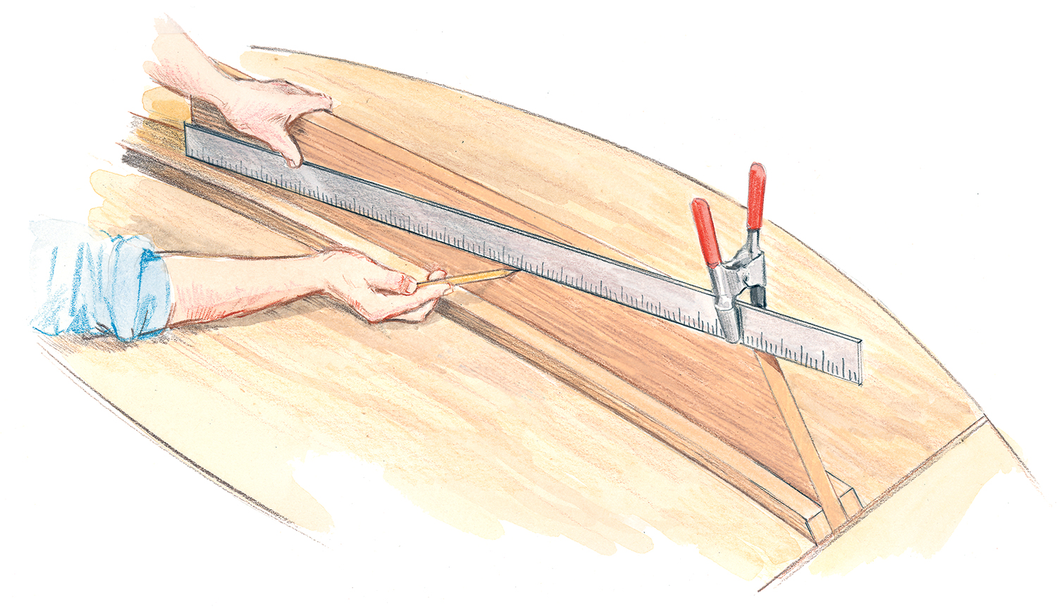
Measure along the bottom from the tip of the inner stem to the aft edge of the transom, and add an inch; this is the rough length of the keel, which is built of 3⁄4″ x 3″ straight stock. Draw a centerline along the length of the keel and cut a 1⁄2″ -wide, 45″ -long slot for the skeg. The keel retains its full 3″ width from the transom to just forward of the skeg. Then it tapers in a straight line from its full 3″ width to 1″ at its forward end.
After sawing the taper, install the keel by drawing a centerline on the bottom of the boat from stem to transom, then two parallel lines, 1 1⁄2″ either side of it. These lines provide a reference so you can correctly position the keel. Temporarily screw the keel to the stem and transom, and then trace its outline onto the bottom. Remove the keel and drill small (say, 1⁄ 16″ ) pilot holes through the bottom inside the guidelines. Next, apply glue, reposition the keel, drill appropriately sized holes from inside the boat, and screw the keel tightly against the bottom from the inside of the hull. Put some small 1⁄ 2″ spacers in the skeg slot beforehand to ensure that the skeg will fit snugly.
3. Make and install the skeg
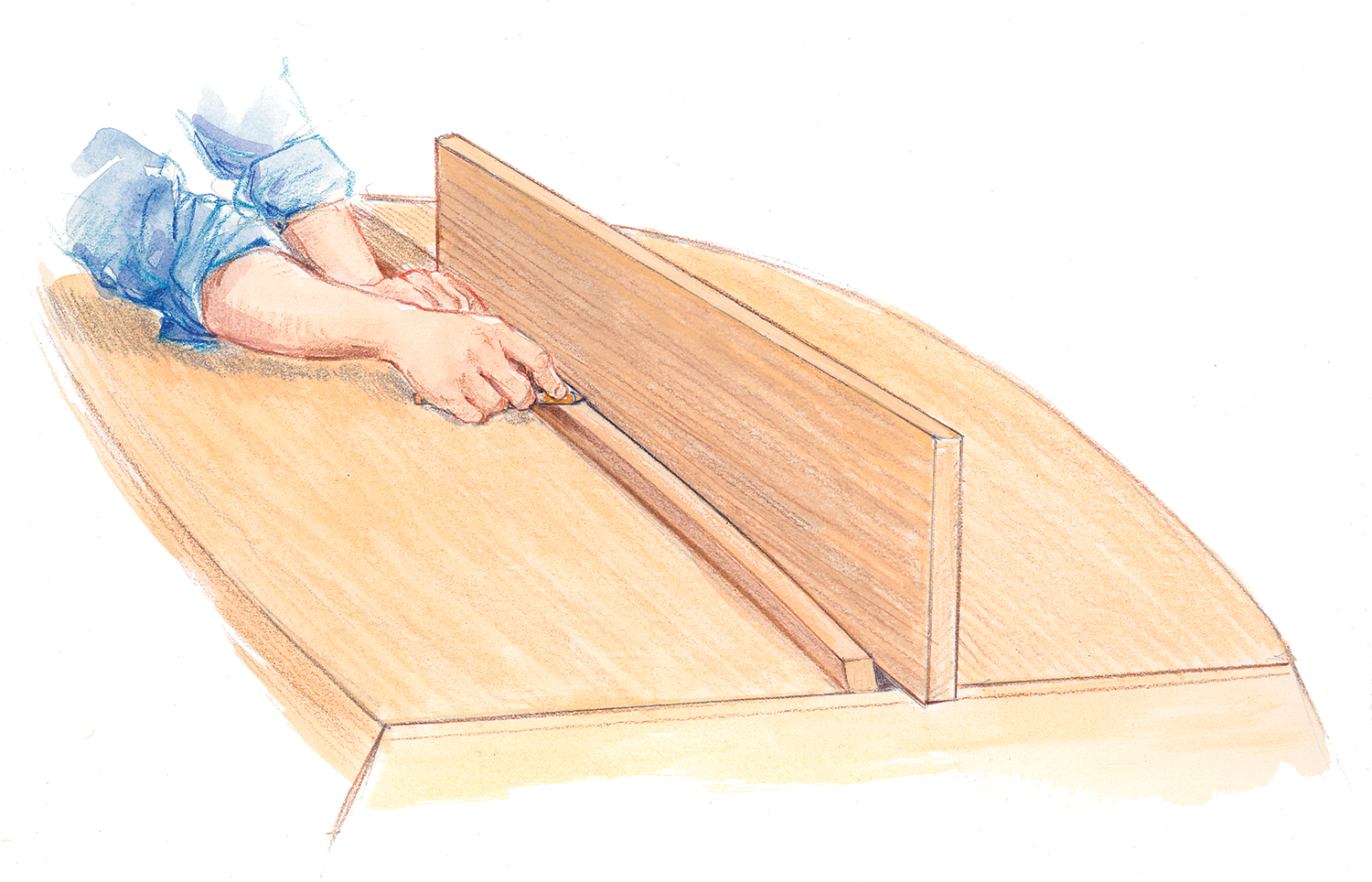
Cut a rectangular piece of 1⁄2″ plywood, 2″ longer and slightly taller than the finished skeg, whose dimensions are given in Part I. Tuck it into the slot in the keel, about 1⁄4″ deep and all the way forward. With your pencil resting on the keel, draw a line along one side of
the skeg, describing the curve of the bottom. Saw the skeg to this line and place it back into the slot, tapping it down in full contact with the bottom. With a straightedge resting against the transom, mark the aft edge of the skeg and cut to that line. With the skeg back in the slot, measure from the bottom up the aft edge and mark the proper height (7″ ). Clamp a straightedge at that mark and at the forward edge of the skeg where it disappears into the keel. Mark and cut to that line. Put a generous radius on the skeg’s aft corner so the 1⁄2″
brass half-oval can easily bend around it.
Coat the contact surfaces with glue, and screw the skeg into the slot from inside the hull. Epoxy and nail or screw a 4′ length of half-oval onto the skeg to cover its entire edge, carrying the half-oval up the transom about 1″. I use epoxy to help hold the half-oval and seal the wood, because I put on the half-oval before painting.
The Outer Stem & Rails
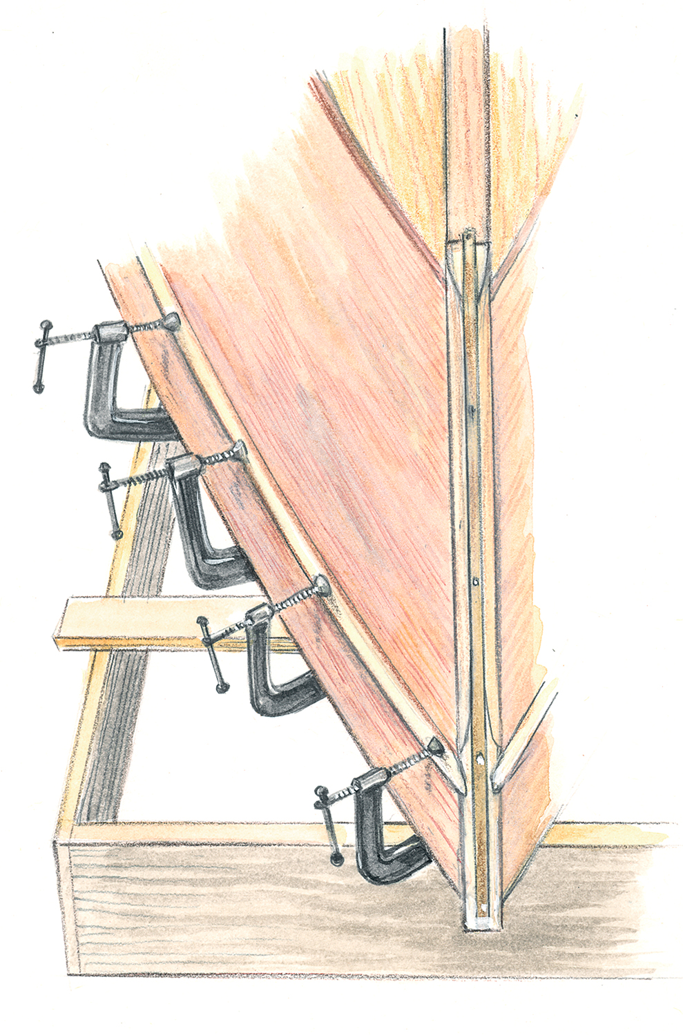
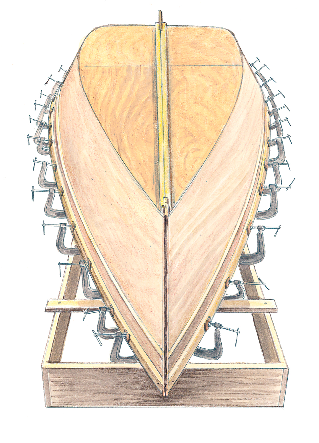
4. Install the outer stem
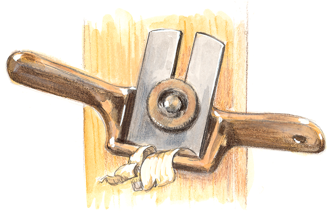
 Plane the forward edges of the topside planking flush with the inner stem; the final width of the inner stem’s forward face should be 1″. The outer stem either can be shaped on the bench or after it’s been fastened to the hull. Draw a centerline on the forward face of the outer stem and two parallel lines 1⁄4″ away from it, creating a 1⁄2″-wide face for the brass half-oval. Using a block plane or small spokeshave, plane a flat from each of the marked lines back to the planking, creating a simple, rolling bevel. But leave the top 6″ unplaned so it remains the full 1″ x 11⁄2″ cross-section, and bore a 1⁄2″ hole through it for the painter. A similar process is illustrated in Volume 1 of Getting Started in Boats, “Building the Lumberyard Skiff” (WB No. 191).
After beveling (if you decide to bevel on the bench before installation), attach the outer stem with glue and screws. Finally, epoxy and fasten the remaining 2′ of your 1⁄ 2″ brass half-oval onto the stem.
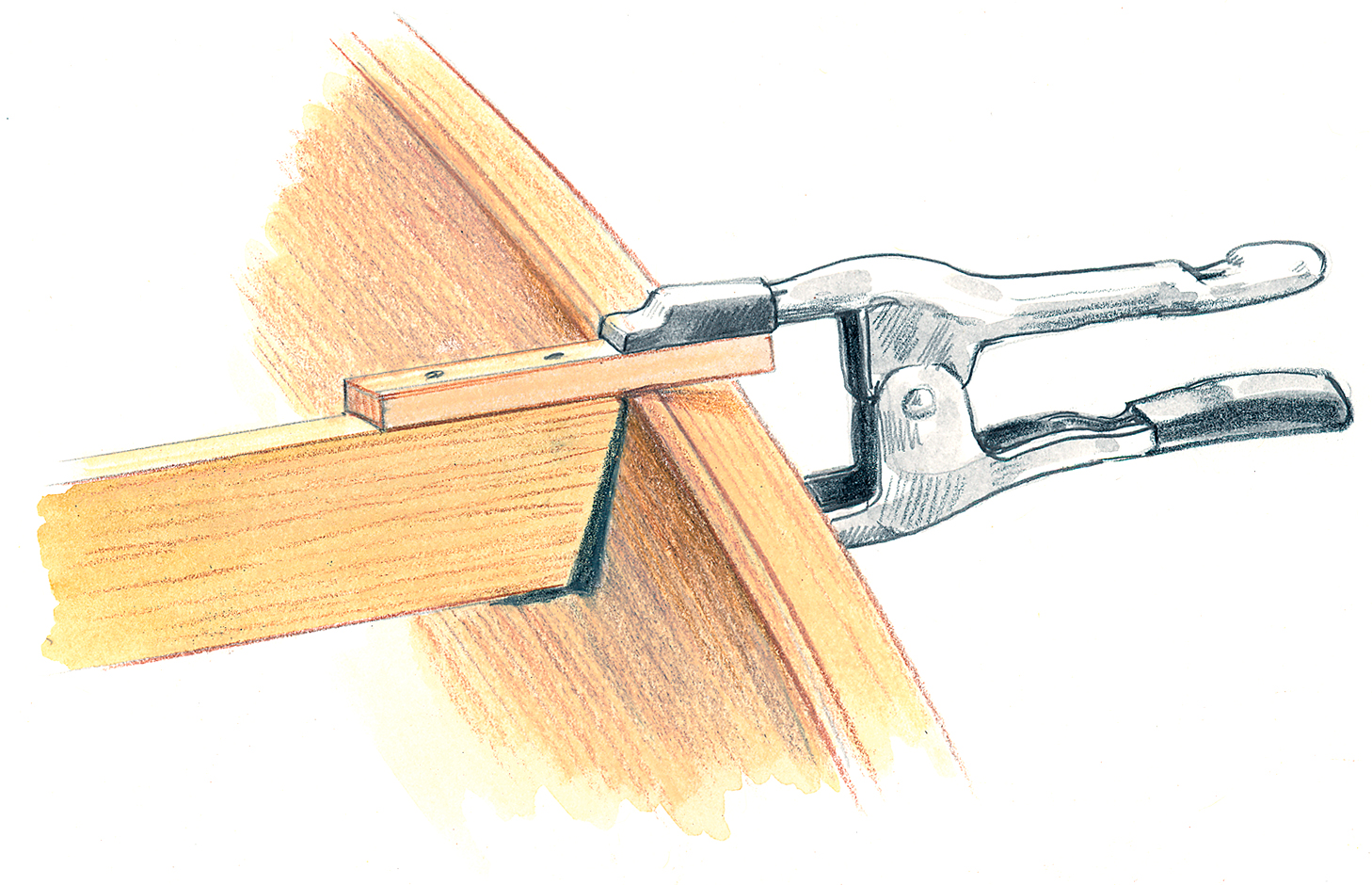
5. Dress up the topsides with halfround
Placing a 1⁄2″ (or 3⁄4″ )-wide pine halfround about 4″ below the top of the sheer is a good way to dress up the topsides on slab-sided skiffs; most lumberyards carry this. Trim the topsides flush with the sheer ribband with a laminate trimmer or block plane. Then, using a combination square, mark a line 4″ (measured vertically) away from the sheer from stem to stern. Bevel the forward ends of the half-round to land against the unbeveled upper part of the outer stem. Glue and clamp or screw (with small screws, predrilled and countersunk from
the inside) the halfround onto the topsides.
6. Make and install guardrails
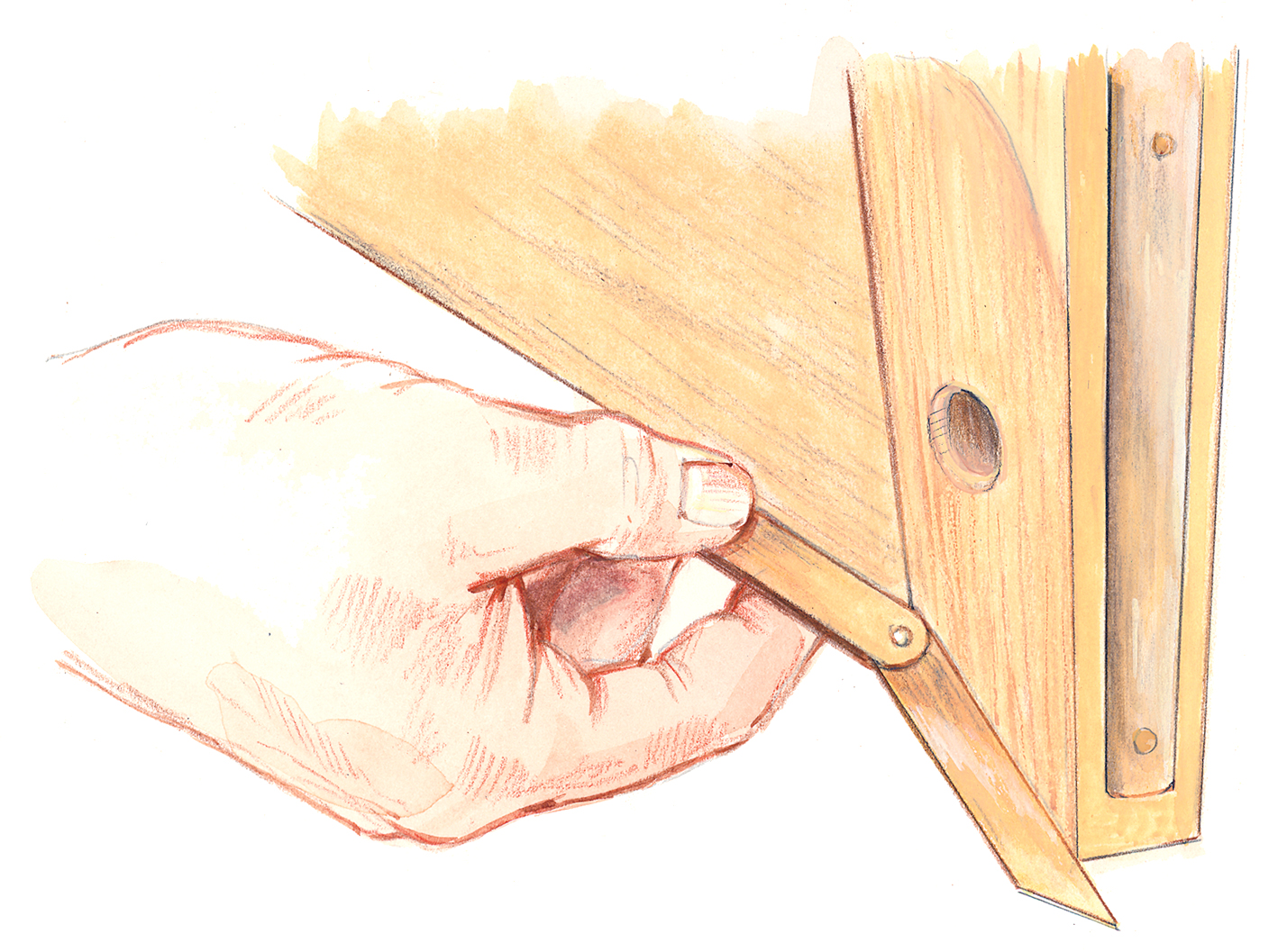
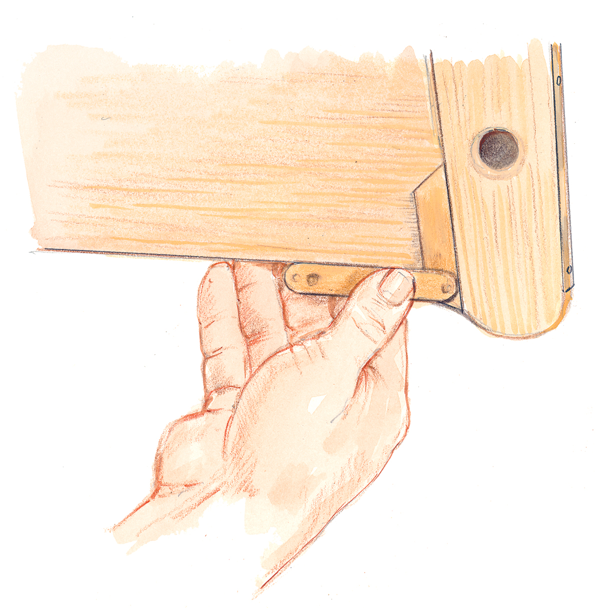
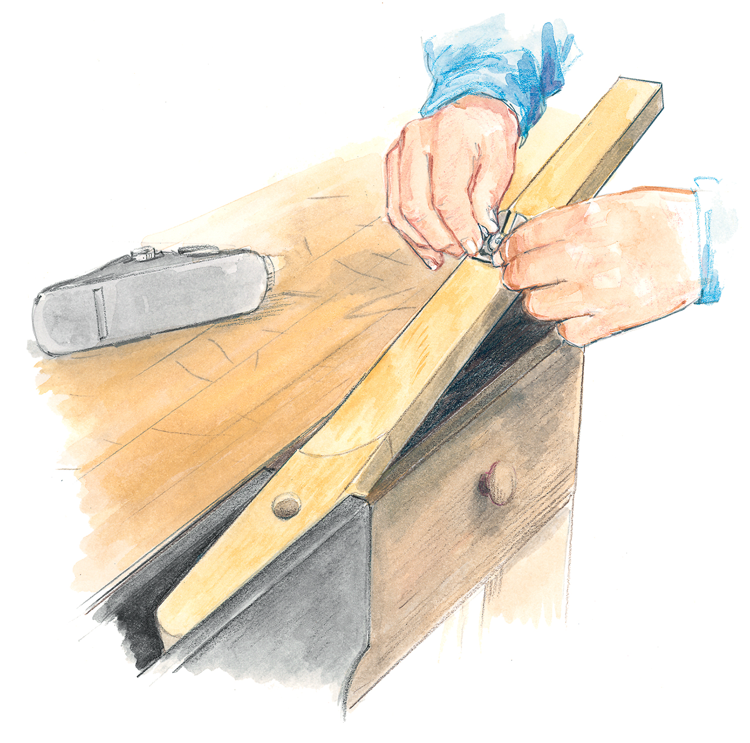
Mill the rails, leaving them at least 1′ longer than the hull. Their dimensions should be 1 1⁄4″ x 3⁄4″ and they should come out of 16′ stock. Bevel the forward ends of the rails to allow them to land on the outer stem. To do this, hold a small bevel gauge against the topside planking parallel with the sheer, the blade against the side of the outer stem. Transfer this angle to the bottom edge of the rail.
Next, hold the gauge along the top edge of the sheer plank and copy the angle between it and the stem face. Mark this angle on the sides of the rail at the forward and aft ends of the line previously marked. Cut to these lines with a sharp backsaw. With a little luck, the rails will lie tightly against the outer stem. If you are off a bit, plane them to fit.
Glue and clamp the rail to the topsides using 11⁄2″ No. 8 screws at the stem and transom. Trim off the extra length at the transom and round over the ends.
The basic hull is now complete, but before it comes off the jig, crawl underneath and trace the station mold locations onto the planking, chines, and bottom. These marks will make it is easier to locate frames, seats, and oarlock positions later on. This is also a good time to chamfer what will be the bottom corners of the guardrails or, if you prefer, round them over. I like to sand the hull while it’s still upside down and fastened to the building jig. Also, this is a good time to apply a primer coat of paint.
7. Remove the hull from the jig
Crawl under the hull and unscrew the chines from all of the chine blocks. The hull is now ready to be lifted off of the jig. This is an exciting time for builders. Sometimes the hull gets accidentally glued to the jig in places and needs to be coaxed off with some lifting pressure. When it lets go, there sometimes is a loud pop.
8. Make spreaders to keep her shape
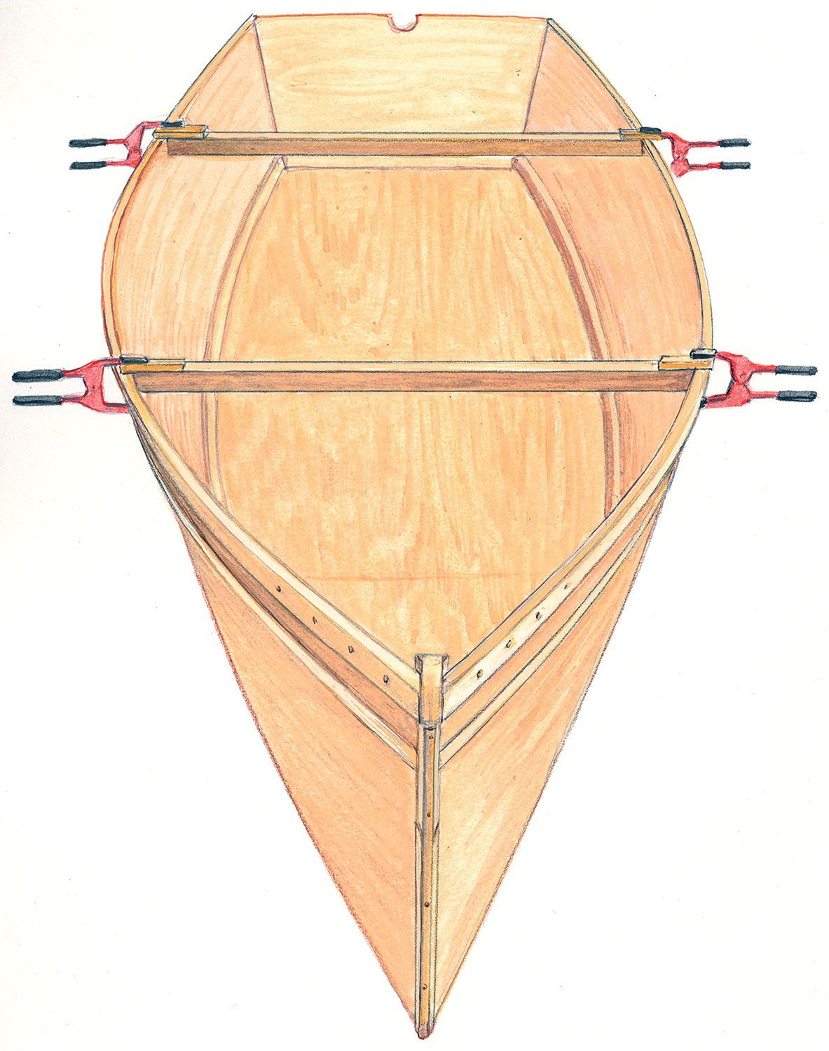
With the hull off the building jig and sitting upright, the sides tend to fold inboard, distorting the sheerline. To prevent this, make a couple of spreaders. Measure the correct beam at stations No. 2 and No. 4 from the building jig or from the plans, then cut two 1 x 2s slightly longer than the boat’s beam at those stations, copy the angle of flare, and cut them to length. Clamp them to the rails so they spread the hull back out to its proper beam. These spreaders will remain in place until the seats are fastened in to take over their function.
Completing the Interior
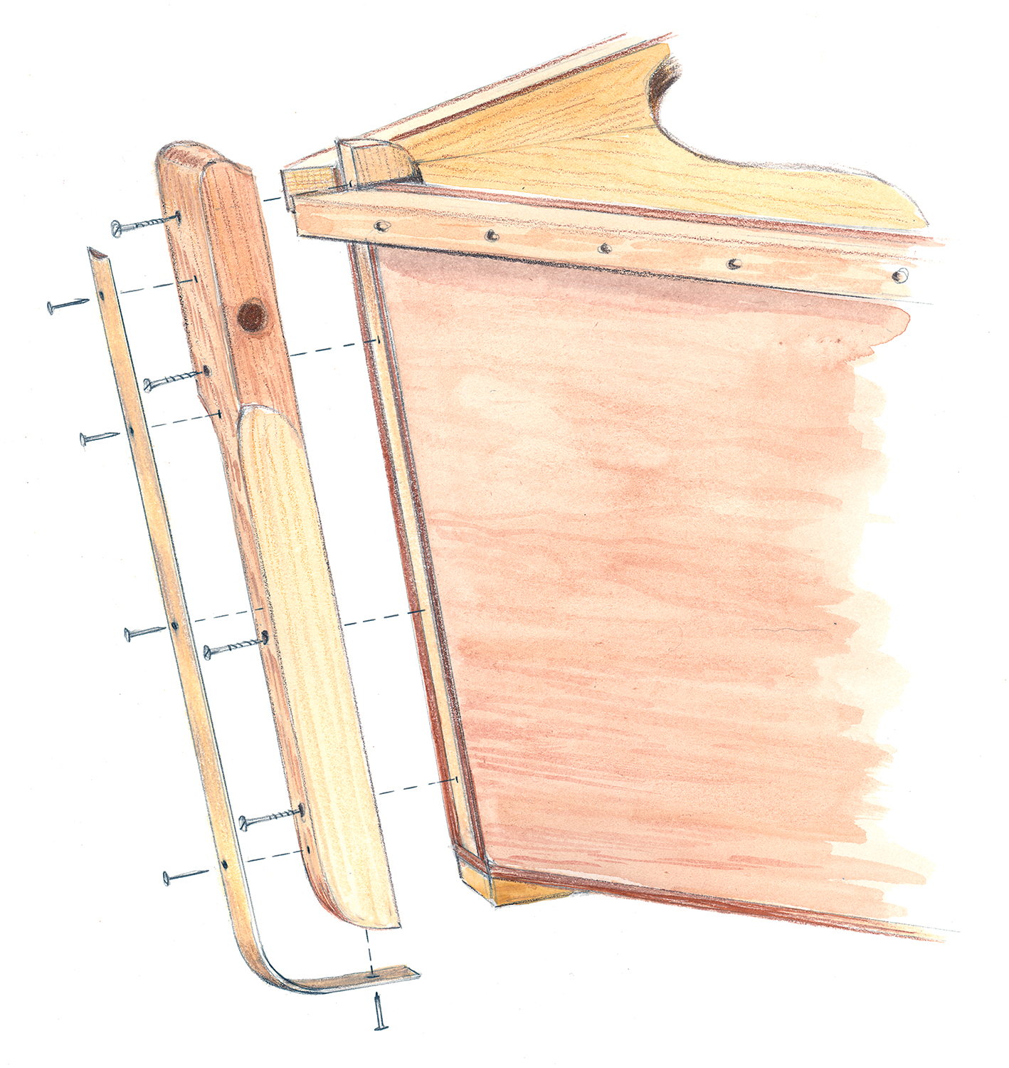
9. Make and install quarter knees
The quarter knees and breasthook should be made from 5⁄4″ stock. I used pine for these. The grain of each quarter knee runs fore and aft, parallel with the rails. The quarter knees on this hull each measure 10″ along the rail and 5″ across the transom. The bevel at the
rail should allow the knee to slope upward, parallel to the top edge of the transom. To determine the bevel of the quarter knee at the
transom, place the bevel gauge on top of the rail with the blade pointing down and slide it to the transom. Cut the two quarter knees, and
fit and fasten them to the boat using four, 1 1⁄2″ No. 8 screws (two through the guardrails and two through the transom).
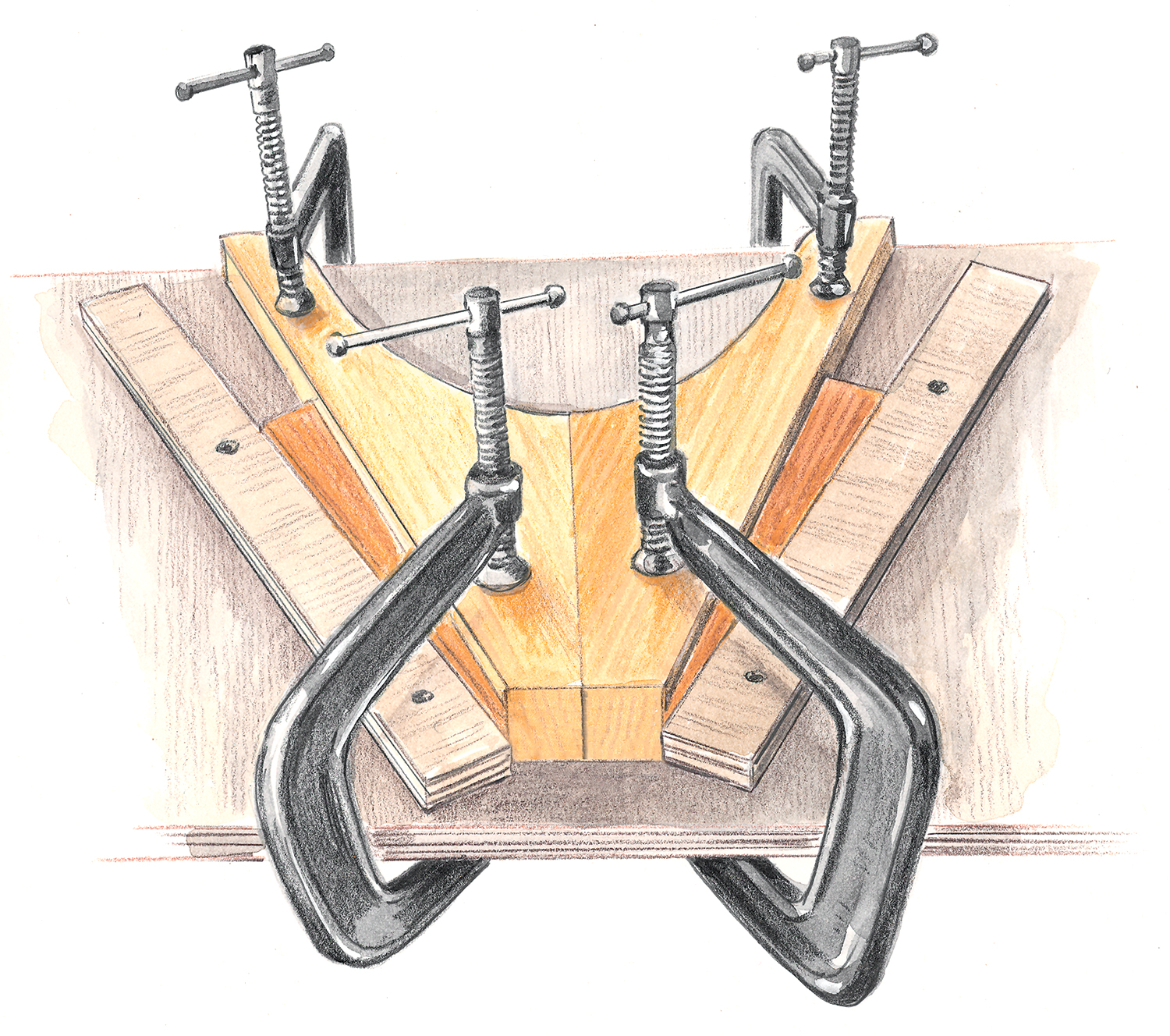
10. Assemble and install the breasthook
The grain of each half of the two-piece breasthook runs parallel with the rails. The breasthook measures 15″ along the rail and, at its aft end, the span across the hull is 16″.
Begin by making an oversized blank, one side at a time. From 5⁄4″ pine stock, cut a plank that is about 18″ x 10″. Hold it up to the stem with the grain running parallel to the rail, and clamp it on top of and overhanging the rail. Cut the forward end so it will butt against the inner stem. Use a straightedge to draw a centerline (that parallels that of the boat’s) aft from the midpoint of the inner stem, and cut to that line.
Using that side of the breasthook as a pattern, make its mirror image. Glue both sides together along their centerlines and, when dry, center the breasthook blank on the rails and push it forward to touch the inner stem. Reach underneath and trace the planking shape on its underside. Saw it out, leaving the line. When the breasthook’s forward end has been fitted against the stem, bevel its sides to fit the flare of the hull. If you take too much off the sides and the fit is loose, remove some stock from its forward end. If you remove too much stock here, plane a little off the sides. With a little patience it will fit snug and you can go on to cut and shape the curves on the rest of it for a comfortable handhold. Install it with epoxy and screws (1 1⁄2″ No. 8, four per side) driven through the rail. Be sure to leave it about 1⁄4″ proud above the top of the rail so there’ll be enough wood for a gentle crown. A flat breasthook is not appealing to the eye, and neither is one with too much crown.
11. Frame out the hull
The sharp corner of the chine won’t hold paint well, so to avoid chipping, soften them before installing the frames. Plane a 1⁄8″ chamfer
on the top inboard corner of the chines; a small trimming plane works great for this. Then, sand the chamfer to a radius with 80-grit paper.
The frames are straight sticks made from 5⁄4″ stock. Each frame has a 3⁄4″ x 1 1⁄8″ notch. The 1 1⁄8″ notch height leaves 3⁄8″ gaps at each
frame along the top of the chine that allow water to drain and not get trapped at the chine, frame, and plank intersection. The frame should fit tight to the inboard face of the chine and plank. The top end of the frame gets a gentle radius; a soup can makes a good template.
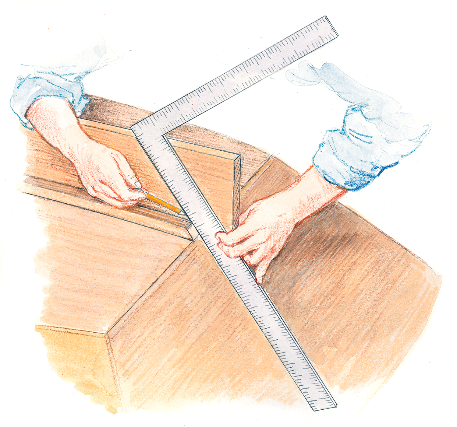
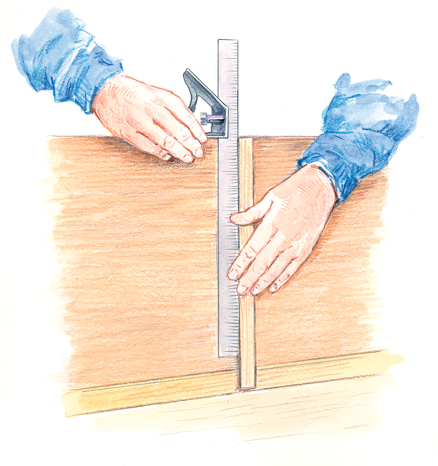
The station mold lines that you drew on the topsides before lifting off the hull provide references for locating the frames, but these lines are plumb, so if the frames followed these lines they would not look quite right. Instead, install them perpendicular to the sheer.
Using a square on the rail with the tip of the blade on the drawn line where it intersects the bottom and chine at each mold location, draw a new line square to the sheer, where the frame should land.
Once all these pencil lines have been drawn and the frames have been made and dry-fitted, drill pilot holes from the inside. Glue and screw the frames in place. For each frame, put four 1″ No. 8 screws through the topsides, one through the rail, and the last one driven through the frame and into the chine. You may need to use slightly longer screws at the top and bottom.
12. Make and install seat risers
 Mill out the 3⁄4″ x 2″ seat risers. Leave them long enough to run past the end frames by about 3″. Bevel their tops to accept the seats and radius the ends. To determine the bevel, screw the risers to the frames at the proper heights from the bottom. Place a straightedge across their tops at the center seat location. Copy the angle between the straightedge and the hull planking, remove the risers, and saw or plane the bevel. The bevel will change slightly forward and aft of this location and can be adjusted with a plane.
Once the seat risers are permanently installed, I chamfer the frames from the top of the riser to the top of the frame including the radius. I make the chamfer about 3⁄8″ wide.
13. Seats
Seats can be made either of 3⁄4″-inch solid stock or plywood. Make them wide enough to be comfortable—at least 11″. They should be long enough to run past the riser by 1⁄2″ or so, but not touch the hull sides. Their ends should be beveled to more or less match the angle of the planking. Install them with 13⁄4″ No. 12 screws driven into the risers. Should the boat be lifted by a seat, those big screws won’t come out. Angle the screws to match the seat riser, and try to center the screw in the riser. Once all three seats have been screwed into place, the 1″ x 2″ spreaders can be removed—but keep them on hand for use during painting.
14. Finish the job

The skiff now has all its pieces made and installed. Remove the seats and the seat risers for easier sanding and painting. All the sharp corners need to be chamfered and/or rounded over for a finished appearance and so they’ll hold paint better. Sand the entire hull with 80-grit sandpaper. Then, paint the boat. (An article detailing the painting process will appear in the March issue of WoodenBoat.) After painting, install a pair of oarlocks. Locate their centers 9 1⁄2″ aft of the aft edge of the middle seat. Congratulations, your skiff is now ready to row!
Tom Hill is the Technical Projects manager for WoodenBoat. Plans and kits for the Babson Island 14 are available from The WoodenBoat Store, www.woodenboatstore.com.
Sail & Power
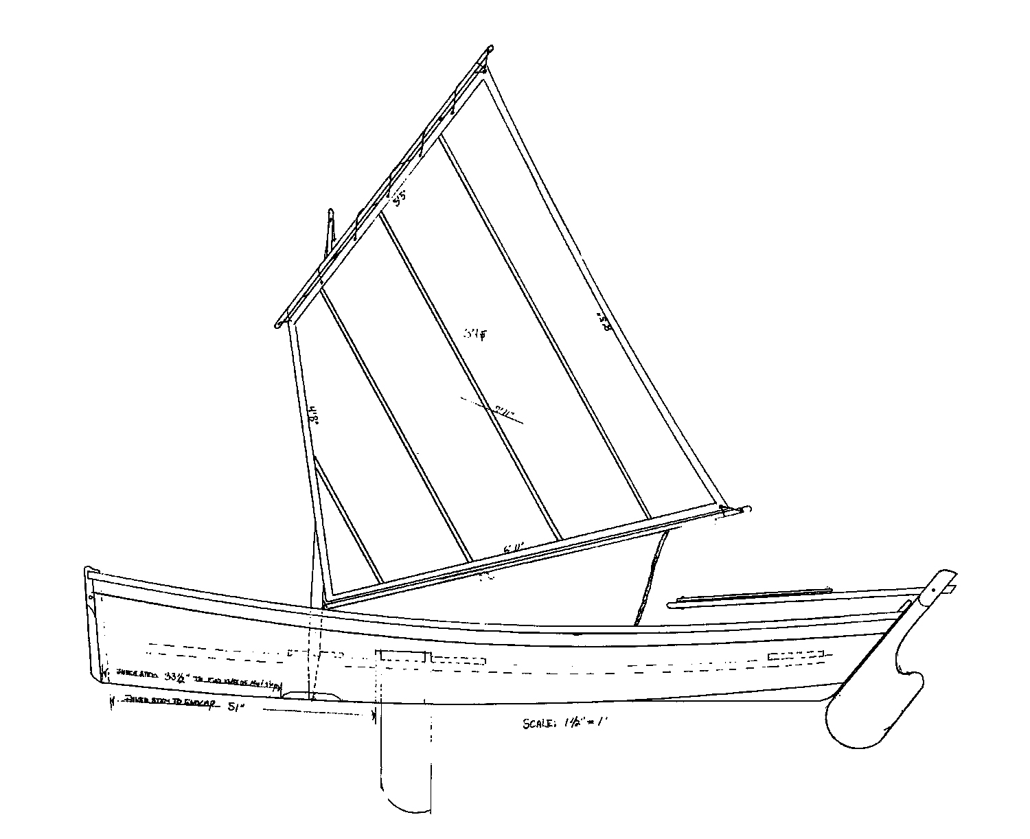
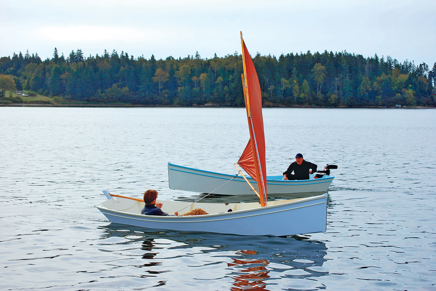
The sailing rig seen here is adapted for the Babson Island 14 from the well-known Nutshell pram—a Joel White design. For its new application, the Nutshell’s mast was lengthened by 6″. This 37 sq ft rig may seem small to some, but the boat moves along nicely in light air. This size sail will give novice open-skiff sailors a little more comfort than a larger rig; the smaller sail allows the boat to stand up in a freshening breeze.
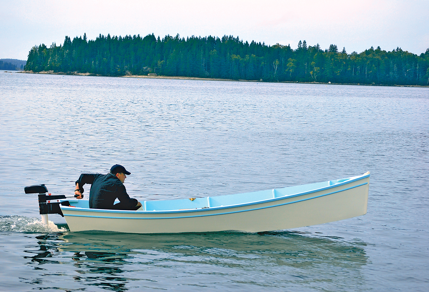
The outboard-powered version in the photograph is driven by a 2-hp Torqueedo electric outboard, and is ideal for exploration and fishing in quiet waters. Its hull form is slightly modified from the rowing-sailing version, and might be thought of as a capacious squaresterned canoe; additional horsepower should not be used.