Learning to read boat plans can help you happily select the boat you want to build or buy. Unpleasant (and expensive) surprises might be avoided, and the process almost always proves entertaining.
Designers, when creating their plans, attempt to represent three-dimensional boats on twodimensional sheets of paper or flat computer screens. They employ four basic sets of drawings: the sail plan (or profile), the arrangement plan (accommodations), hull lines, and the construction drawings. After you have studied them all with a trained eye, you should have a good idea of how the boat will go together, how it will look out on the water, and how well it will perform. You can do this in the comfort of home or shop, without the need for getting dirty or parting with much cash.
Sail Plans and Aesthetics
The first drawing to catch our attention likely will be the sail plan…or, if we’re looking at a powerboat, the outboard profile. This rendering will form our first impression of the design’s aesthetics. What should we look for? Boat design remains as much art as science. What appears fine to my old and prejudiced eyes might not appeal to you, but at some point we might find common ground. Let us agree that no matter the style, good proportion among design elements leads to eye-pleasing objects. Also, on boats, the fairness (smoothness) of visual lines prevents any jarring of the eyes.
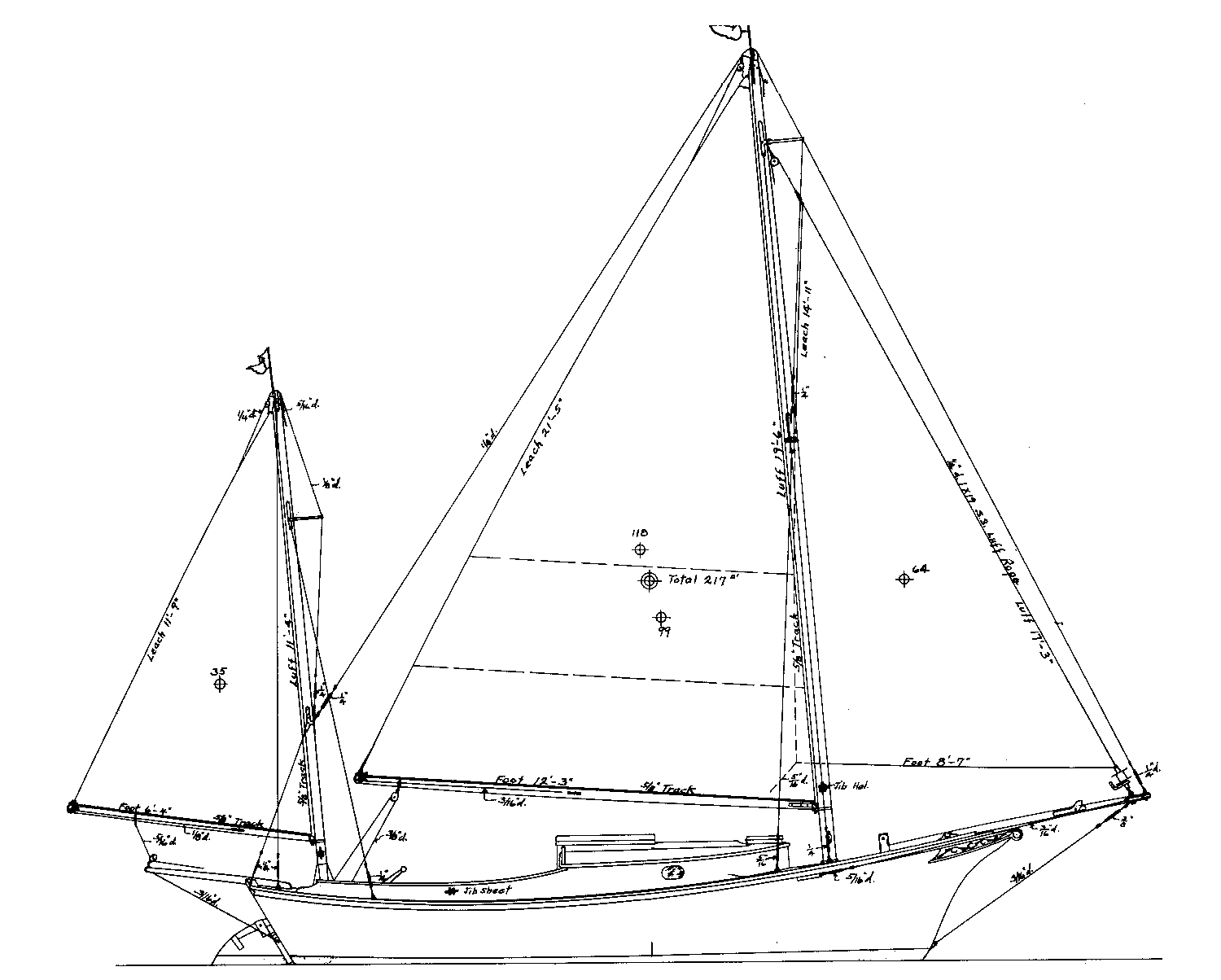
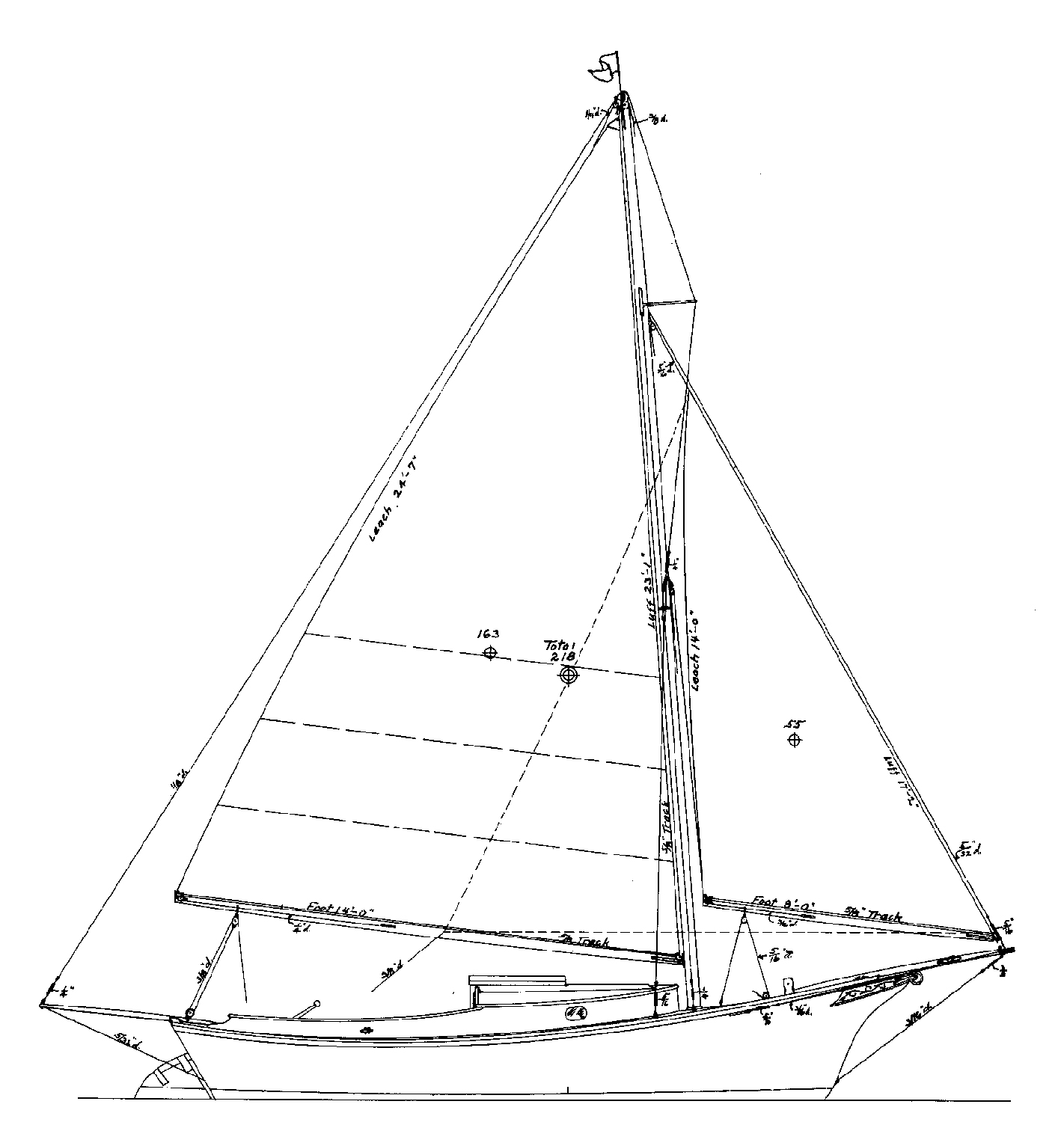
Where to start? Let’s look first at the sheerline…the sweeping longitudinal curve of the hull at the gunwale. A traditional sheerline tends to be highest at the bow and drops to its low point amidships, or as much as three-quarters of the way to the stern. This shape works well in a sea, and often proves easy to build in the shop. Today, for reasons of function or style, we see all types of sheerlines: reverse (higher amidships), powderhorn (S-shaped), and straight. The boat with a straight sheerline will prove tougher to plank up than you might think. On the water, a straight sheer hardly ever appears straight. It assumes various curves as we see the boat from changing perspectives. Some of these views can be less than flattering (ah, there’s that prejudice). I hope you’ll agree that Sam Crocker drew a striking traditional sheerline for Sallee Rover, the good 20′ yawl or sloop shown here.
The next features we will notice might be the stem’s curvature (or lack thereof) and the shape of the stern. The choice here is overwhelming, but perhaps we can agree the curves of changing radius (as opposed to circle arcs or straight lines) often prove interesting and attractive.
Deckhouses, or cabins, tend to look better if they are low and mate well visually with the hull. Drawing tall houses that also are handsome can prove a challenge, but towering structures seem more attractive— or less offensive—when placed farther aft (more prejudice).
The rig should suit its hull functionally and aesthetically. Racing rigs tend to be tall and narrow (partially due to rating rules). Working and cruising rigs usually are lower and spread out forward and aft. A boom that is cocked-up at its after end looks good (yes, indeed, yet more prejudice) and is less likely to trip us in hard conditions (that’s a fact). Designers draw booms that droop aft in order to circumvent decadent rating rules…or, perhaps worse, simply to follow modern fashion.
Can we find any absolutes in this business? Well, we might start by studying sail plans from old (say, 50 to 100 years) designs. The boats that still please our eyes might tell us something. You could find that those drawn to a purpose age better than those drawn to a style.
Hull-Lines Drawings
Folks new to reading boat plans seem to view the hull-lines drawings as tough to decipher. Not so…and once understood, these most fascinating of all boat drawings provide much information. They let you “see” the shape of a hull. Please study this section more than once, and try to visualize the threedimensional Sallee Rover as you go.
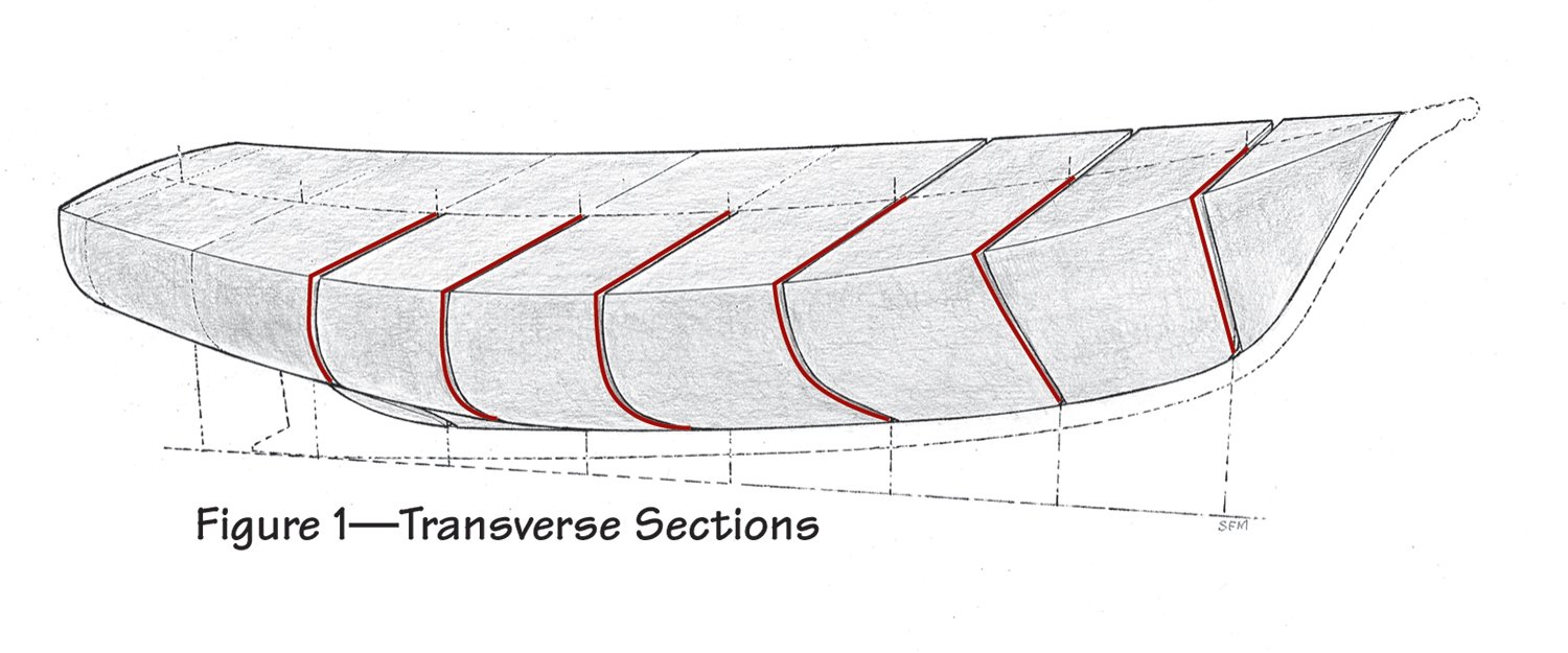
Boat design used to, and sometimes still does, begin with a wooden model of a hull. Imagine, if you will, taking such a model and slicing it as a loaf of bread, but with fewer and thicker slices (see Figure 1). Working to a common centerline and baseline, trace the outline of these slices or sections on a piece of paper. The resulting drawing (inset, Figure 5) gives a picture of the hull’s shape as seen from the bow or stern. As a rule, the designer shows only half of each section— relying upon the builder to produce a reliable mirror image. All of the half-sections are presented in a single drawing, the body plan. Typically, the right side shows the hull as if it were coming at you. The left side represents the view looking forward from the boat’s wake.
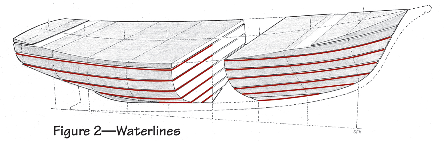
In your mind’s eye, reassemble the wooden model. Now slice it again, but this time cut the hull horizontally into layers (Figure 2). Trace the shapes of these slices (waterlines) on paper using a common centerline. This drawing shows the hull as seen from below (Figure 5). Look at it much as you would study a contour map.
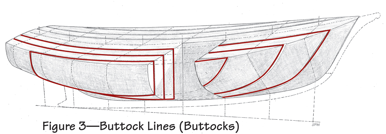
Once again, put the model together with imaginary glue. Run your make-believe saw vertically and longitudinally through the hull (Figure 3). The shapes revealed by these cuts are the buttock lines, and they can be traced as were the other lines (Figure 5).
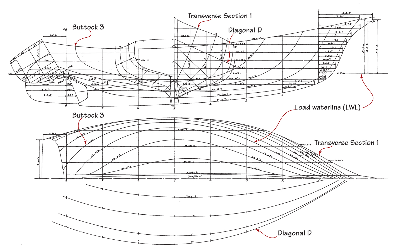
All of the lines described above appear in their own views as curves. They also show up in the other views, but they are seen there as straight lines. That is to say, the sections display their shape in the body plan, but appear as straight lines in the elevation (profile) and waterlines (half-breadth) views. The shapes of the other lines in various views should yield to study of Figure 5.
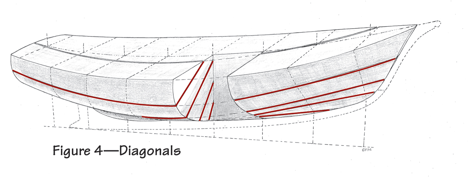
Although the three sets of lines we’ve discussed define the shape of a hull, designers almost always include a fourth set called diagonals. Diagonals (Figure 4) emanate from the centerline in the body plan as straight lines that intersect the curved section lines at more or less right angles. And therein lies the key to the diagonals’ value. Nearly perpendicular crossings provide the greatest accuracy for fairing a set of
lines (making sure that there are no humps or bumps in the hull shape and, in fact, that a real hull shape exists), whether on the drawing table or, at full scale on the loft floor.
After you’ve digested the above and believe you know Sallee’s shape, turn to Sam Manning’s perspective drawing on page 7. Did the picture in your mind match the real boat? If not, more practice seems in order. Study all the lines plans you can find. The exercise will prove good fun.
Offsets
If you’re looking at a full set of plans (rather than “study” plans), the designer likely will have included a table of offsets. He developed this
chart of numbers by taking measurements from the freshly drawn hull-lines. His triangular-sectioned architect’s rule automatically scaled these dimensions to full-sized measurements. And this clever device will let you determine the size of berths, amount of headroom, and other crucial dimensions directly from the drawings. (Architects’ rules or scales are available from The WoodenBoat Store and drafting supply houses for only a few dollars. They have no moving parts, last forever, and are well worth the investment.)
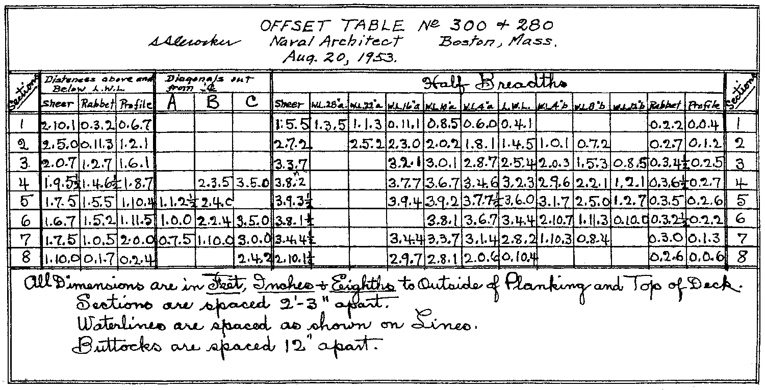
Offsets usually are measured from the hull’s centerline out and from a baseline up or down to points on the outboard surface of the hull. For Sallee Rover, Sam Crocker chose to use the load waterline (LWL) as the baseline. Measurements traditionally are given in feet, inches, and eighths. The first numbers in Sallee’s offset table (height from the baseline to the sheer at Station No. 1) read 2.10.1, which translates as 2′ 101⁄8″. You’ll become accustomed to this notation more quickly than you might think. Yes, it would be simpler if the whole world would go metric, but that’s not likely to happen anytime soon.
Arrangements and Construction
An arrangement (accommodations) plan can be toured as would a floor plan for a house, but we need to keep in mind the general lack of straight lines and cubical space aboard a boat. A house plan might show a closet or cabinet hard against an outer wall. A berth aboard a boat if drawn flush with the gunwale on the two-dimensional arrangement plan likely would hang impossibly outside the hull in three-dimensional reality.
Some small cruising boats are drawn with too many berths. Six people cruising aboard a 24-footer seem unlikely to remain friends. And take note of the toilet arrangements, unless you like the idea of sleeping with the commode parked below, or adjacent to, the head of your berth…a common arrangement aboard small sailing cruisers.
The convertible (to berths) U-shaped dinettes found on some cruising sailboats don’t work well either for sleeping or eating when the boat is heeled down or dealing with rough seas. They’re fine in the harbor. If you plan to eat while sailing, consider other arrangements—such as a dropleaf table hung from a centerboard trunk.
Designers usually present the arrangement and construction drawings separately. Sallee Rover’s accommodations are simple: Two adequate berths (with stowage below) and a centerboard trunk. Period. Sam Crocker elected to present the accommodations and construction details in the same set of drawings.
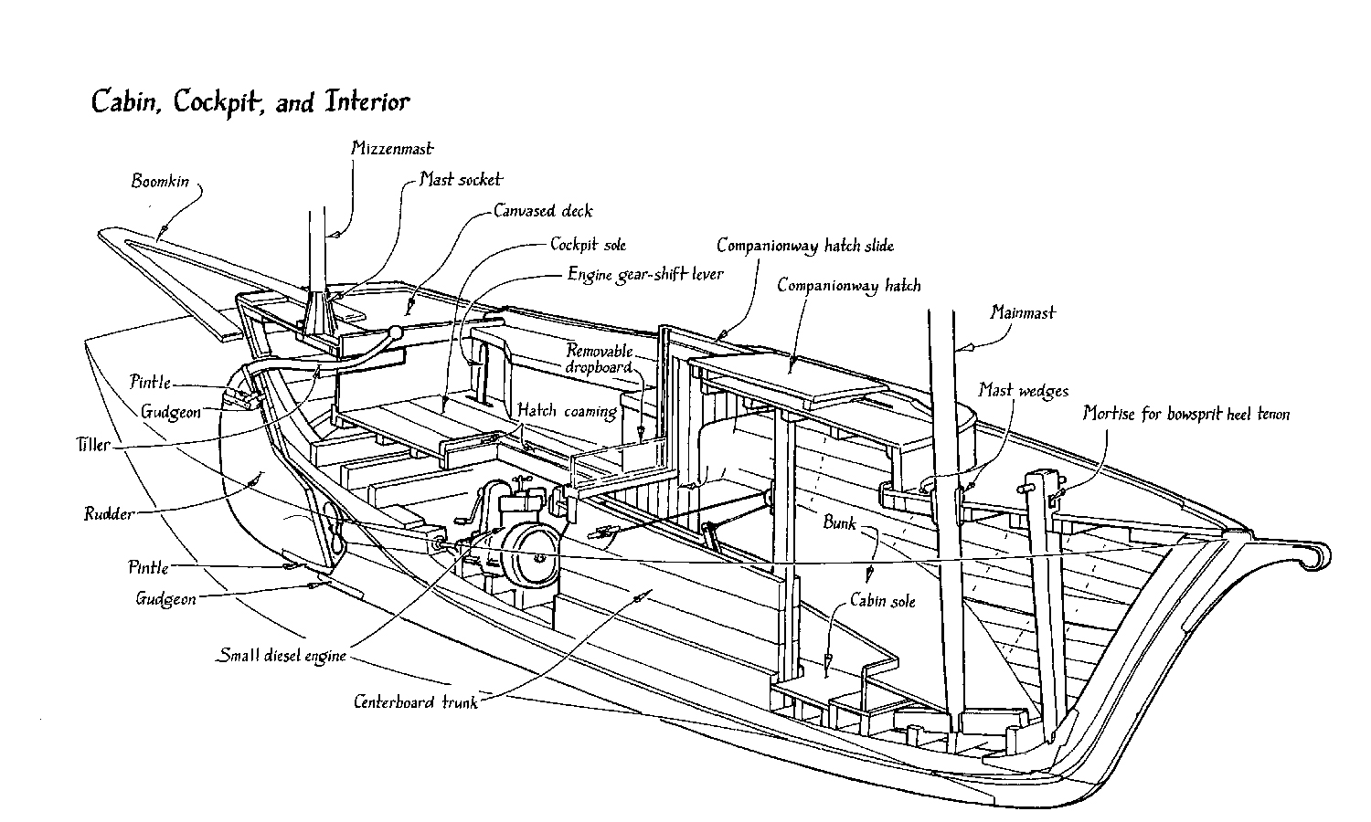
To gain some idea of the actual space aboard Sallee Rover, study the two-dimensional arrangement/ construction plans shown on the cover and compare them to Sam Manning’s cutaway perspective view of the cabin, cockpit, and interior above.
The construction drawings tell us how all the pieces go together. Details not found on the drawings likely will appear on typed specification sheets that accompany the plans.
The Results
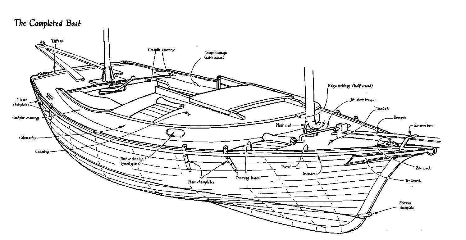
This striking perspective rendering shows us the sum of the drawings we’ve seen here. Few sets of boat plans will include this satisfying amenity. But if we spend some pleasant hours studying sail plans, hull lines, arrangements, and construction plans, then this final picture will come effortlessly to mind.
Mike O’Brien is boat design editor for WoodenBoat. He also writes and publishes Boat Design Quarterly magazine, a collection of boat plans and commentary. Special thanks to Crocker’s Boatyard. Sam Manning’s perspective illustrations seen here are available from The WoodenBoat Store on a poster, which includes several additional drawings. Sam Crocker’s complete building plans for Sallee Rover are available from the store at www.woodenboatstore.com and from Crocker’s Boatyard at www.crockersboatyard.com.
By the Numbers
Given the numbers (often listed as “Particulars”) that accompany almost every boat plan, here are some design ratios that might help predict a boat’s performance.
Even if you disliked high-school algebra, these equations will prove simple enough to solve with an inexpensive scientific calculator (available at most supermarkets and drugstores for less than $10). In any case, don’t let this arithmetic spoil your day. You can skip the following section and return to it when you feel more mathematically inclined.
SAIL AREA/DISPLACEMENT RATIO measures a boat’s sail power versus its weight. It gives an indication of a boat’s ability to overcome wave-making resistance, which becomes more significant as boat speed increases. Some texts tell us that this ratio serves as a yardstick for a boat’s speed potential in heavy air. Considering the army of variables that the formula ignores, it is a rough measure at best. SA/D ratios below 14 are considered “low,” 14–17 “moderate,” 18–21 “high,” and those above 21 are “very high.”
Here’s how to calculate the Sail Area/Displacement Ratio:
1. Divide the displacement (the weight of water displaced by the floating boat) by 64.0 lbs/ft3 (the “weight density” of seawater). The result expresses the displacement in cubic feet as asked for in the formula.
2. Take the displacement (ft3) to the 2 ⁄3 power. If you have a scientific calculator, simply punch in the displacement, hit the y x button, followed by .667, and you’ve got it.
Lacking a proper calculator, you should square the displacement and take the cube root of that number—using tables (such as found in Skene’s Elements of Yacht Design) or whatever method your math teacher preferred.
3. Divide the sail area by the result from step No. 2 above to get the ratio.
SAIL AREA/DISPLACEMENT RATIO FOR SALLEE ROVER
SA/D = Sail Area (ft2)/Displacement (ft 3)2/3
SA = 218 sq ft (from the Sail Plan or Particulars)
Displacement = 3,825 Pounds (from Particulars)
Displacement (ft3) = 3,825 lbs/64lbs/ft3 = 59.77
D2/3 = 15.28 (ft 3)2/3
SA/D = 14.27
An indicator of light air potential is the ratio of Sail Area to Wetted Area SA/WA. In general, SA would be the measured sail area and WA is the total surface area of the hull and rudder below the waterline. A ratio of about 2.5 indicates good light air performance. The wetted area is that area of the boat below the waterline and includes the rudder. Not all designers include this in their particulars.
SAIL AREA/WETTED AREA RATIO
SA /WA = Sail Area (ft2) /Wetted Area (ft2)
SA = 218 sq ft (from the Sail Plan or Particulars)
Wetted Area = 109.9 sq ft (from plans, not shown)
SA/WA = 1.98
DISPLACEMENT/LENGTH RATIO indicates “heaviness” relative to a boat’s waterline length. Boats with D/L ratios greater than 300 are considered “heavy,” 200–300 “medium,” 100–200 “light,” and designs with D/L ratios below 100 are “ultralight.”
DISPLACEMENT/LENGTH RATIO FOR SALLEE ROVER:
D/L = Displacement (Long Tons) /(.01 LWL)3
Displacement (lbs) = 3,825 (from Particulars)
Displacement (Long Tons) = 3,825 lbs/2,240 lbs /ton = 1.71
LWL = 16.83 ft (from Particulars)
D/L = 358
BALLAST/DISPLACEMENTRATIO gives some indication of a boat’s relative stability (if the designs being compared have similar hull forms and vertical centers of gravity). B/D ratios below 30% are considered “low,” 30–40% “moderate,” 40–50% “high,” and those above 50% are “very high.” Since Sallee Rover has no ballast keel, the ratio doesn’t apply to her. Still, it’s good to know the equation for boats that have one.
DISPLACEMENT/LENGTH
B/D = Ballast (lbs)/Displacement (lbs)
For the most part, numbers can be trusted. The application of numbers sometimes deserves our suspicion. These ratios can serve as tools for comparing similar designs, but to evaluate a boat on the basis of a tenth of a point here or there would be foolhardy in the extreme.
If a particular design displays highly unusual ratios for its type, it might represent a major contribution to the state of the art. On the other hand, we could be staring directly into the gaping maw of disaster. These simple numbers cannot explain everything, but they can wave red flags indicating areas worthy of further study.