Beginners Guide to Boat Particulars and Numbers
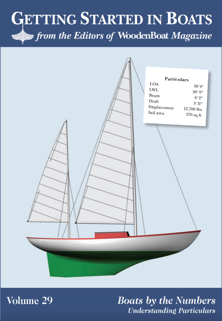
Open nearly any article or review about a boat, or look at the plans for one, and you will probably find a chart or table near the title headed “Particulars,” “Principal Dimensions,” “Principal Characteristics,” or something similar. A list of abbreviations and numbers will come under this heading. In this edition of Getting Started in Boats, I hope you’ll gain an understanding of what some of these particulars mean and how they can lead you to a clearer interpretation of the boat in question.
Boats and yachts can be described either subjectively or objectively. Subjective descriptions like “long,” “wide,” “beautiful,” and “seakindly” (the list can be endless) are opinions and judgments that will vary according to the writer’s and the reader’s connotations and personal experience. The objective route will leave little or no doubt to a precise meaning. Saying that the load waterline (LWL) is 29′ 7″ or the beam is 11′ 51⁄2″ allows you to visualize the boat in a concrete way. Some particulars describe specific characteristics that are not visible, such as stability, and many are used to compare the boat to others of similar design.
While not all particulars fit tightly into a specific category, for efficiency we will segregate them into five broad areas:
1. Dimensional numbers, such as the LOA (length overall).
2. Numbers that indicate stability, such as MTH1° (moment to heel one degree).
3. Ratios that can be used to compare similar boats, such as DLR (displacement-length ratio).
4. Numbers that show the locations of geometric centers—LCB (longitudinal center of buoyancy), for example.
5. Coefficients of form, of which Cp (prismatic coefficient) is one.
Often, you’ll see only a few specifications, such as those shown in the article on the Argie 15 on page 89 of WoodenBoat No. 221 where only six are listed. A lack of space prevents us from providing a complete description of all possible particulars, but we will cover the most common ones in this article. Understanding the concepts and the vernacular surrounding particulars will prepare you to make objective, as well as subjective judgments as you study boat plans. Having a good understanding of the particulars will deepen your knowledge of how boats work and will take you a long way toward selecting the best boat for your needs.
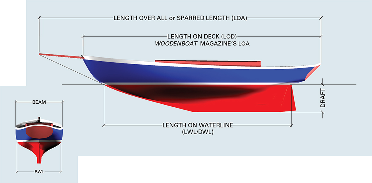
The terms length overall (LOA) and length on deck (LOD) can be confusing. Following longstanding tradition, WoodenBoat defines LOA as a boat’s hull length, not including spars. Some others will call hull length the LOD and refer to the sparred length as LOA. Beam is less controversial; it is always measured at the widest part of the boat. The widest part is often at the sheer but, depending on the boat, may be in another location.
The terms length overall (LOA) and length on deck (LOD) can be confusing. Following longstanding tradition, WoodenBoat defines LOA as a boat’s hull length, not including spars. Some others will call hull length the LOD and refer to the sparred length as LOA. Beam is less controversial; it is always measured at the widest part of the boat. The widest part is often at the sheer but, depending on the boat, may be in another location.
Dimensional Numbers
Length Overall (LOA) was historically the length of the hull proper and did not include any overhanging spars such as booms and bowsprits. Today it has often come to include any overhanging spars such as bowsprits and main or mizzen booms if they extend beyond the hull proper. WoodenBoat magazine uses the length of the hull, and not the sparred length, to denote LOA.
Length on Deck (LOD) is the length from the end of the bow to the aft end of the main deck.
Load Waterline (LWL) is the length of the waterline as the boat is floating in the water. Usually the LWL is slightly different from the Designed Waterline (DWL), which is the waterline that the designer intended the boat to float on. The designer and builder both strive to make the LWL and the DWL as close to each other as possible.
Beam, Beam Overall, and Beam at the Waterline (B, BOA, BWL) are the widths of the boat taken at certain locations on the hull. Beam or B is the maximum width of the hull itself. The BOA is the boat’s width over any fixed projections from the hull, such as rubrails and channels. BWL is the maximum width of the waterline, taken either at the LWL or the DWL. Again, these measurements (LWL and DWL) should be very nearly the same.
Draft (D) is the depth of the boat in the water from the LWL to the bottom of the keel.
Displacement (Disp, Δ) is a boat’s volume by weight—Archimedes’ principle in action. If you had a large tank of water filled to the rim and placed a boat in it, the weight of the overflow or “displaced” water would equal the weight of the boat. Therefore the weight of a boat is equal to the weight of the water it displaces. Displacement can also be stated in volume, expressed in cubic feet (ft3) of the displaced liquid (see Centers and Coefficients illustration below). The displaced volume will be different depending on whether the boat is in salt or fresh water, but the boat’s weight will remain the same.
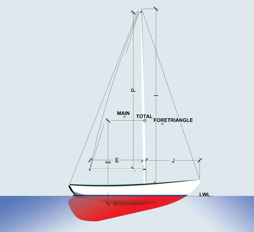
Sail Area = Main + Foretriangle
Main = 1⁄2 P × E
Foretriangle = 1⁄2 I × J
P = Distance from top of boom to black band at head of mast
E = Distance between aft side of mast and black band on boom
I = Distance between fore side of mast at deck (4% of beam at mast above sheerline) and the top of the highest jib or spinnaker halyard block
J = Distance from fore side of mast at deck to intersection of head stay and deck centerline
⊕ Indicates a center
Sail Area (SA) is the designed or measured sail area is a counterintuitive concept. Instead of being the actual area of the sails used on the boat, it is based on dimensions taken from specific locations on the mast(s), boom(s), rigging, and hull (see illustration). Sail plans will also show the geometric centers of the sails and the center of the total sail area, which is the so-called Center of Effort (CE). Its height above the center of the underwater profile illustrated above is called the Heeling Arm (HA).
Upright Stability is measured by the Moment to Heel 1° (MTH1°). As this moment increases in roughly a straight line up to 20 degrees of heel, it can also be used as an indication of sail-carrying ability.
Ratios That Compare Similar Types of Boats
Sail Area to Wetted Area (SA/WA) is an indication of how well a sailboat will perform in light air going at relatively slow speeds because skin friction is the predominant form of resistance at low speeds. The Wetted Area is the total square feet of hull and appendages (like a rudder and skeg) in contact with the water. Classic boats will have a SA/WA range of about 1.9 to a little over 2.5. Modern high-performance sailboats may have higher numbers.
Displacement/Length Ratio (DLR or DL) is used to compare the relative weight of similar boats that have different DWLs. It also is an indication of how easily (or not) a hull will go through the water. In general, heavy displacement boats need more horsepower per pound of displacement to go a given speed than their lighter cousins do. One exception to this is a heavy boat that has less wetted surface than a light boat and is going at slow speeds for its length.
In America, the DLR is found with the formula DLR = D(LT) (displacement in long tons) divided by the cube of 1/100 of the LWL (load waterline), or D(LT)/(0.01LWL)3. Let’s look at an example, given a 25′ LWL sailboat with a displacement of 12,000 lbs. Each LT has 2,240 lbs, so 12,000/2,240 = 5.36 LT. 5.36/(0.01 × 25)3 = 343. The range of DLR varies from about 50 or 60 on the ultralight side to over 400 for a tugboat or deep-sea fishing dragger. Today a sailboat with a DLR of 343 would definitely be considered heavy for her length.
What’s a Long Ton (LT)?
One long ton is 2,240 lbs. One short ton (like a ton of coal in the U.S.) is 2,000 lbs. The long ton is used to measure a boat or ship’s displacement. It works out to be 1.12 times a short ton or 35 cubic feet of salt water with a density of 64 lbs./cu ft.
Measuring Sail-Carrying Ability
The Dellenbaugh Angle is a measure of the sail-carrying ability of a sailboat. It is equal to SA (sail area) × HA (heeling arm)/MTH1°. The smaller the Dellenbaugh angle, the stiffer the boat. For classic keelboats in the 20′ to 40′ DWL range, the Dellenbaugh angle will vary between about 15 to 24 while more modern boats will have their Dellenbaugh angles about 25 to 30 percent lower.
Another measure of sail-carrying ability is the Wind Pressure Coefficient (WPC). The WPC is measured at 20° and is equal to MTH20°/(SA × HA). The WPC is the reciprocal of the Dellenbaugh angle, measured at 20 degrees. The higher the WPC, the stiffer the boat will be. The corresponding range for classic sailboats is 0.7 to 1.3.
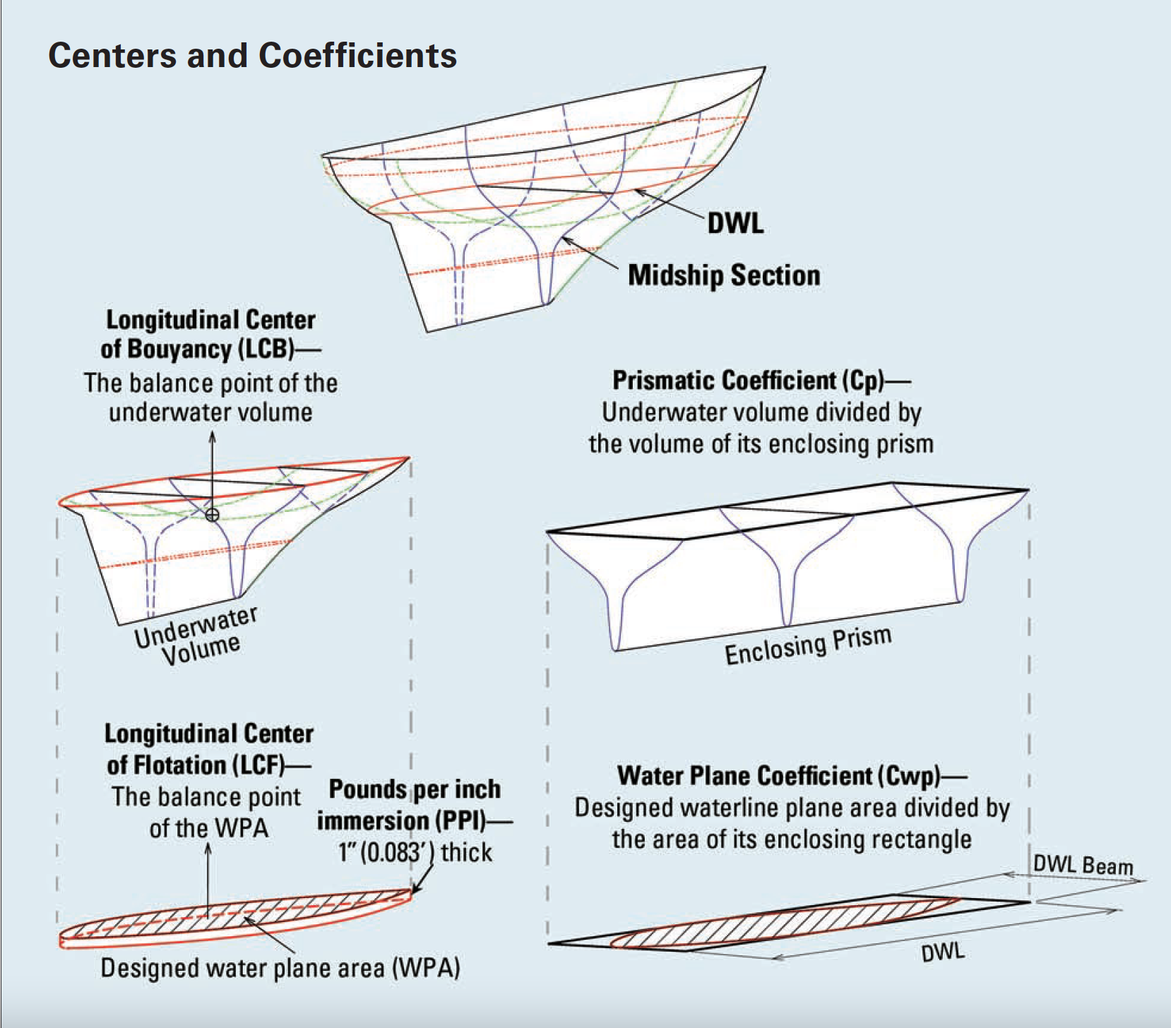
Coefficients of form such as the prismatic coefficient (Cp) and geometric centers such as LCB are not visible but are important to give you an understanding of a boat’s shape.
Geometric Centers and Coefficients of Form
Geometric Centers
Longitudinal Center of Buoyancy (LCB) is the fore-and-aft position of the geometric center of the underwater volume of the hull (see illustrations, opposite page). It is usually expressed as a percentage of the DWL from its forward end. There are optimal positions for the LCB depending on the designer’s desired performance for a boat.
Longitudinal Center of Gravity (LCG) is the fore-and-aft balance point of all the weights that make up the boat and, like LCB, it is often expressed as a percent of the DWL. If you move from the cockpit to the bow, the LCG will move slightly forward.
In still conditions, the LCG and the LCB will always stay in line vertically. If you move forward, the LCG does also, and the boat trims so that the LCB comes in line with the new LCG.
Vertical Center of Gravity (VCG) is the vertical position of the balance point of all the weights that make up the boat. The VCG is one of the most important factors that affect a boat’s stability. The lower the VCG, the more stable your boat will be, and vice versa. Your dinghy becomes tippier when you stand up because, in standing, you raise the VCG. Always be aware of this principle when moving heavy weights to a higher location in your boat.
Longitudinal Center of Flotation (LCF) is the fore-and-aft position of the geometric center (balance point) of the LWL plane expressed as a percent of the LWL from its forward end. It is the point about which the boat trims in the fore-and-aft direction (see illustration, opposite page). Usually the LCF is located aft of ’midships, so the bow will go up or down somewhat more than the stern when a change of trim occurs.
As mentioned in the introduction, not every particular fits neatly into a single category. Pounds per Inch Immersion (PPI) is one of these. While PPI is a descriptive particular, it is easier to visualize within the context of geometric centers and coefficients of form (see illustration, facing page). Assuming that the boat is floating on or near its DWL, PPI is the amount of weight that, when added to a boat, sinks it 1″ deeper in the water.
To find PPI, multiply the area of the LWL waterplane (sq ft) by 1″ (0.083 ft). Then, multiply by 64 lbs/cu ft if you use your boat in salt water. PPI is useful in coming up with a corrected draft when stores, luggage, and additional items are being loaded aboard.
Coefficients of Form
Coefficients of form give us an idea of how the underwater volume and areas that make up our boat are distributed. Two important ones are the prismatic coefficient and the waterplane coefficient.
Prismatic Coefficient (Cp) is a measure of how full or fine the ends of our boat are. A prism is any volume that has a constant cross section along its length. To visualize the prism relevant to this discussion, slice your boat off along the DWL (as illustrated on the opposite page) and then take a thin slice from the middle of the underwater portion where the cross-section area is the greatest. Now extend this cross section to each end of the DWL. The volume of the extended section will be the area (sq ft) of the slice times the length of the DWL (ft) in cubic feet (see the enclosing prism illustration, opposite).
The Cp is the displacement (see underwater volume illustration, opposite) in cubic feet divided by the volume of our enclosing prism: Cp = Disp/(’midship area × DWL). It is always less than 1 and, as mentioned earlier, is a measure of how full or fine the ends of our boat are. The Cp varies from the low 0.5s to the 0.7s.
For non-planing boats, the Cp is very important For a given Speed/Length Ratio
Coefficients of form such as the prismatic coefficient (Cp) and geometric centers such as LCB are not visible but are important to give you an understanding of a boat’s shape.
(SLR) (speed in knots/sq root of DWL), there is an optimum Cp that produces the least resistance. The optimum Cps were found by experimentation and are explained in books on naval architecture. If you were designing a non planing powerboat with a 25′ DWL and wanted her to cruise at 61⁄2 knots (SLR = 1.3), you would shape the hull so that the Cp would equal 0.62 (0.62 being the optimum Cp for an SLR of 1.3).
Waterplane Coefficient (Cwp) indicates how full or fine the area of the DWL plane is. It is found by dividing the area of the waterplane by its enclosing rectangle. It is always less than 1 and for conventionally shaped sailboats will be about 0.7. To find the approximate Waterplane Area (WPA) of a conventional sailboat, take 70 percent of its waterplane-enclosing rectangle: WPA ≈ 0.7 (LWL × Bwl ).
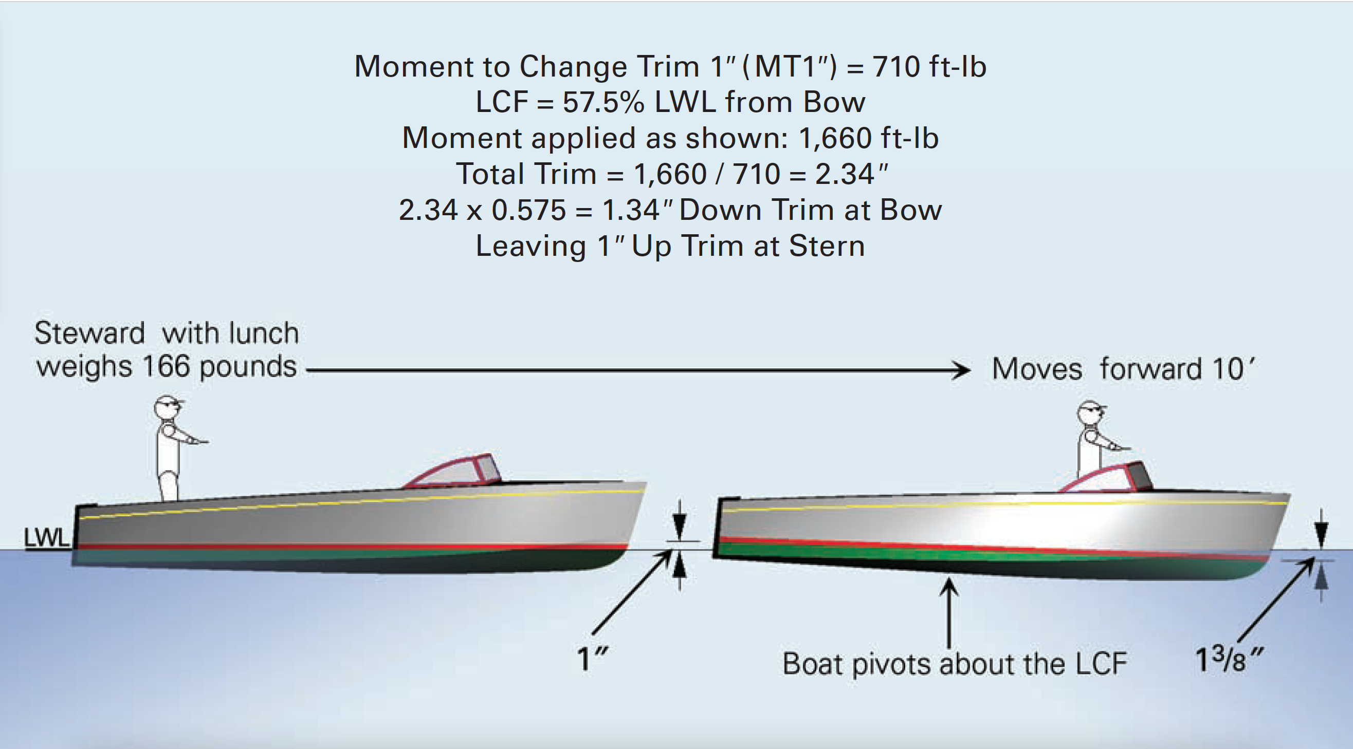
Let’s say your runabout has a MT1” of 710 ft-lbs, you weigh 166 lbs, and the LCF is 0.575 of the LWL from the bow. When you move 10’ forward from the aft end of the cockpit to the forward end, the bow will move down about 13⁄8” and the stern will move up about 1”, for a total of 2 3⁄8”.
Moment to Trim One Inch
Moment to Trim One Inch (MT1″) is thefore-and-aft moment (distance × force) that will cause the bow and stern to move up or down a total of 1″ at the DWL or LWL. The total movement equals the total trimming moment divided by the MT1″.
For example, if the MT1″ equals 1,000 ft-lbs per inch and the total trimming moment equals 2,000 ft-lbs, the total trim would be 2,000 divided by 1,000, or 2″. As the boat trims (seesaws) about the LCF (see page 6), the actual movement at each end will depend on the location of the LCF.
You may approximate the MT1″ for your boat by dividing 35 percent of the WPA (waterplane area) by its beam (BWL), or MT1″≈ 0.35 WPA/BWL.
Walter M. Wales, PE, is a yacht designer, naval architect, and an educator who lives in midcoast Maine.

