Ballast Keel
One of the most fascinating and heartwarming things about the boatbuilding business is the universally friendly helpfulness of the many visitors we have. They are not, for the most part, people with, as you might say, an axe to grind-or a plane to be adjusted, or even a check to press into our embarrassed hand as down payment on a new design. Not at all. They come because they like us, and they like the smells around the shop that speak of cedar shavings, wood preservatives, and certain little creatures who have discovered good digging under the boiler.
These visitors are not ignorant. They are keen students of yacht design and boatbuilding, ever willing to help with a bit of friendly advice, or a quick demonstration of how Manny (whose shop they visited on last week’s day off) fits a beam in less than half the time we’re likely to need for the same job. And when they say, “Do you really think this stuff is fit for planking”-or, ”My gahd, don’t tell me you’re still using iron keels and galvanized bolts!” – we feel properly grateful and almost at a loss for words. Almost, but not quite.
Therefore, having arrived at the subject of ballast keels, and in full awareness of my vow to avoid contention concerning matters of design, I’d like to attempt to justify that hunk of weight, to describe what it’s made of and why it’s shaped the way it is.
Outside iron
There are still some who, steeped in the lore of Friendship sloops, sandbaggers, Brixham trawlers, and seasickness cures, maintain that all ballast should be inside, anyway. I have given up fighting the battle of sail-carrying power (“After all-admit it-if you want to go to windward, you turn on the engine”), and have even stopped pointing out that lead inside is fully as expensive as lead outside, and terribly dangerous if the boat rolls completely over. I even dare suggest that some of those encapsulated-birdshot ballast systems in the plastic boats will bear watching, too. All I do now is give the inside-ballast man a flatiron and suggest he hit the bench with it, twice-once with his hand on top of the iron, and once with his hand underneath. If you have never run a boat aground and feel completely confident that you never will, then this demonstration does not apply; but if you are half as timid and bumbling as I am, you’ll be happy in the thought that the weight is already at the bottom of the pile.
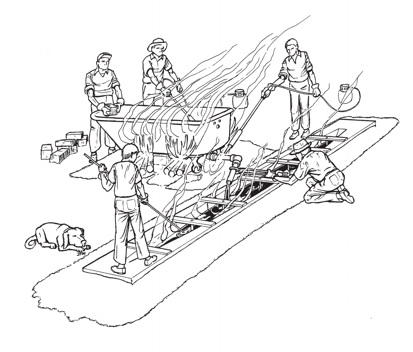
So we’ll put the ballast outside and keep the bilge airy. But why iron? You can melt lead yourself, in an old iron bathtub over burning automobile tires, and ladle it into a wooden mold. If a foundry casts a lead keel for you, in a sand mold, you need only provide the wooden pattern and more money. The weight can be lower, less bulky, more easily located at the correct fore-and-aft position. It won’t rust. The bronze bolts through the lead shoe are more reliable than the steel bolts you’d use through iron (and just to be cautious, I’ll include stainless steel in my doubts). And, as someone always points out, you can take lead ballast off anytime, sell it for scrap, and get your money back.
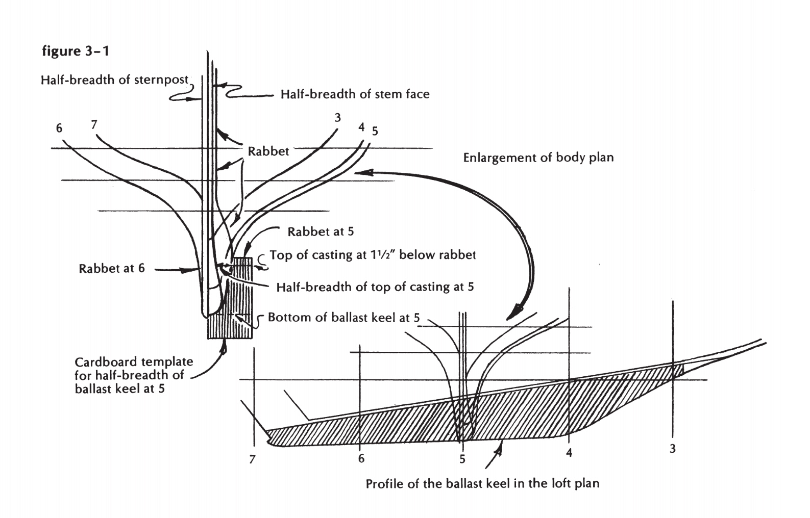
Figure 3-1
In the face of all this undisputed evidence in favor of lead, what can we say in favor of iron? Well, first, it’s less expensive, if compared to the foundry’s price for a lead keel, or if you add your own extra labor cost in making a negative pattern or mold and doing your own melting and pouring-which, incidentally, can be somewhat hazardous, if you get careless; I have scars to prove it. But cost is a poor argument. The best money in the boat is the money that buys outside ballast, so don’t begrudge it. Get the best material, and get enough. In my case, get iron. Design the boat so that only iron can hit those adamantine ledges-and slide smoothly off, undistorted. Design it, furthermore, so that you don’t have to carve out large mounds of outside deadwood, where vile worms will dwell soon after you scrape the paint off. Think how strong the boat must be, with stem, sternpost, and all points between tied directly to that unyielding base. Neither thrust of mast nor two-point support from a storage cradle will ever bend that foundation.
The solid pattern method
Whether your design calls for lead or iron, slabsided or streamlined, someone has to make a pattern for it. Patternmaking is a craft that demands a very high degree of skill, precision, and ingenuity-if you’re dealing with something like a matched pair of water-jacketed engine manifolds, or a massive frame whose finished dimensions must be accurate to tiny fractions of an inch. But such skill is not essential to the making of c;1 ballast-keel pattern, and you have to make a pattern anyway-so let’s get at it.
If your design calls for the simplest form parallel-sided for the greater part of its length, tapering very slightly from top to bottom to give the pattern “draft” so it can be lifted out of the sand-then the problem is very simple. You can make the pattern solid, preferably of whitepine timber sawn to the maximum thickness required at the top of the casting. Pile it up, and
cut it to the profile you laid down on the floor. Taper the pattern for draft by running it through a single-surface planer, with a batten tacked along its lower edge. Double the thickness of the batten, of course, when you turn the pattern over to do the other side. (Or lacking a surface planer, you can do this tapering by hand plane. A taper of 1/4 inch to the foot is enough.)
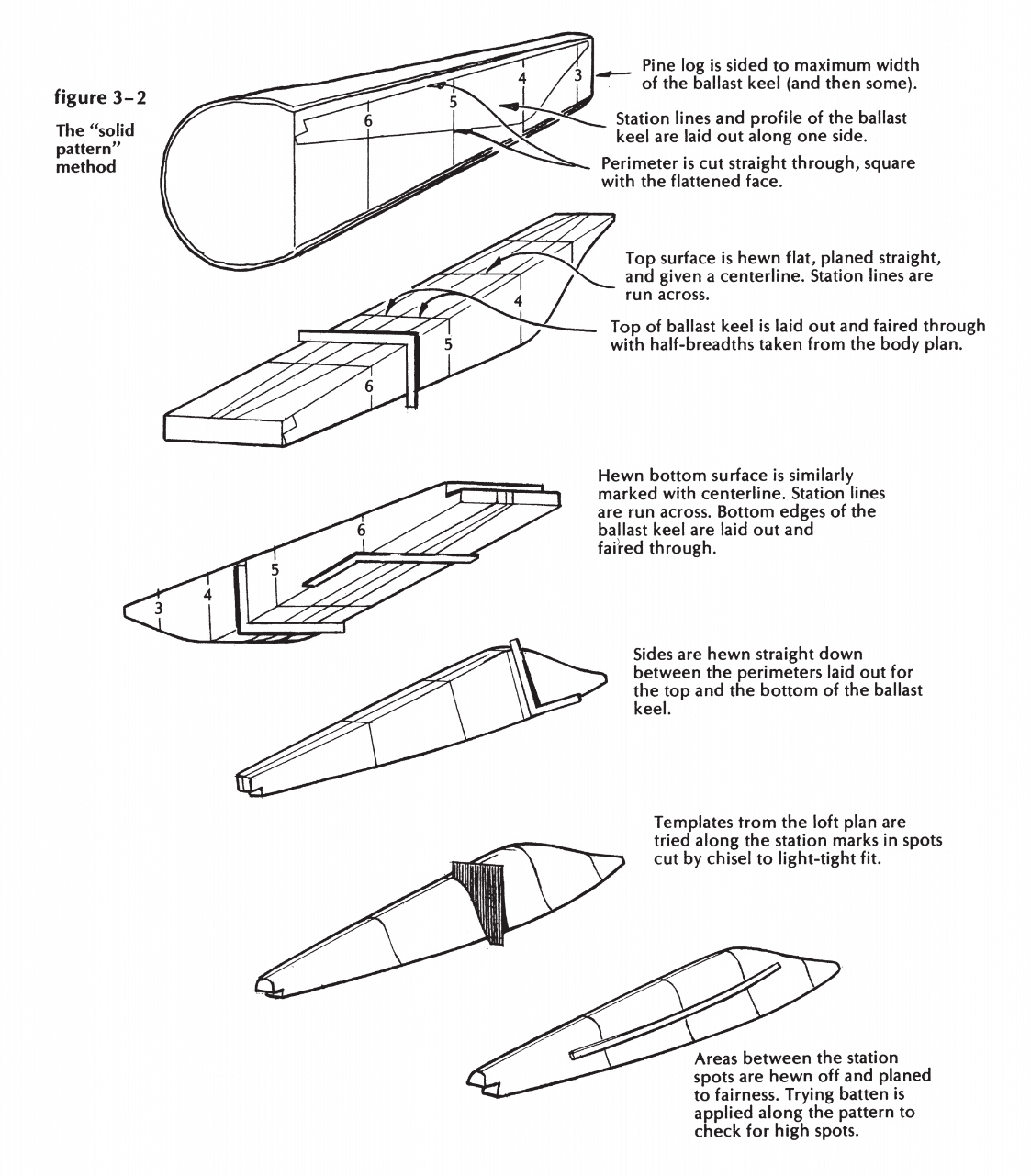
Figure 3-2
Taper the ends of the pattern as necessary, and shape the entering edge as shown in the lines drawing. If your designer has been paying attention to the findings of the tank-research men, he will be very fussy about this, probably demanding a curve like a snubbed parabola, rather than the flat-with-rounded-comers, full half-round, or blunt knife-edge that were considered proper by various designers at various times during the past hundred years. Laminar flow, width and location of maximum chord, acceleration of water particles, minimization of the areas of turbulence-these are all suddenly very much to be considered, and you can be sure that your designer had them in mind when he shaped those lowermost waterlines.
For the moment, let’s ignore the problem of core prints, lifting eyes, and surface finish, and discuss instead the building of a more complicated pattern-for instance, the one required for our example.
There are at least three ways to do this job. The first and most primitive (and by far the most difficult, in my opinion) is to start with an enormous baulk of timber and whittle it to shape, using templates lifted from the section lines in the body plan as guides. (Figure 3-2 illustrates this method step by step.) An oldtime sparmaker, good with broadaxe and adze, could possibly do an acceptable job by this method. So could Michelangelo.
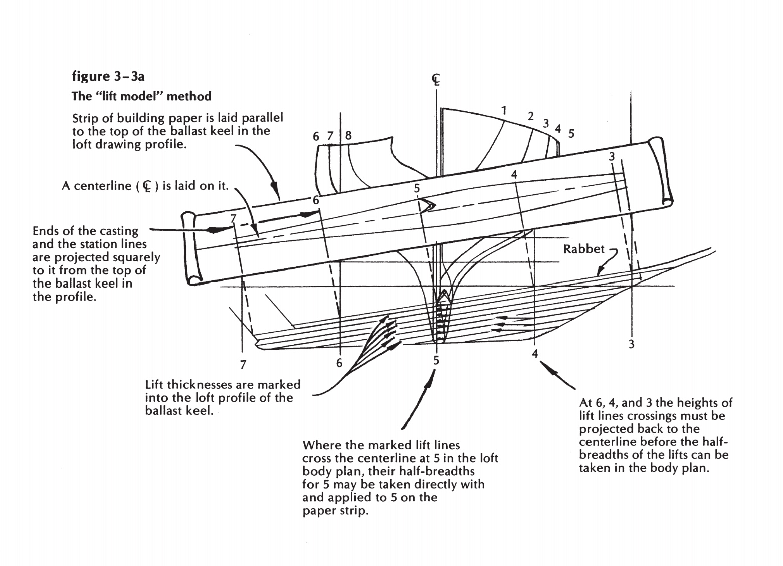
Figure 3-3a
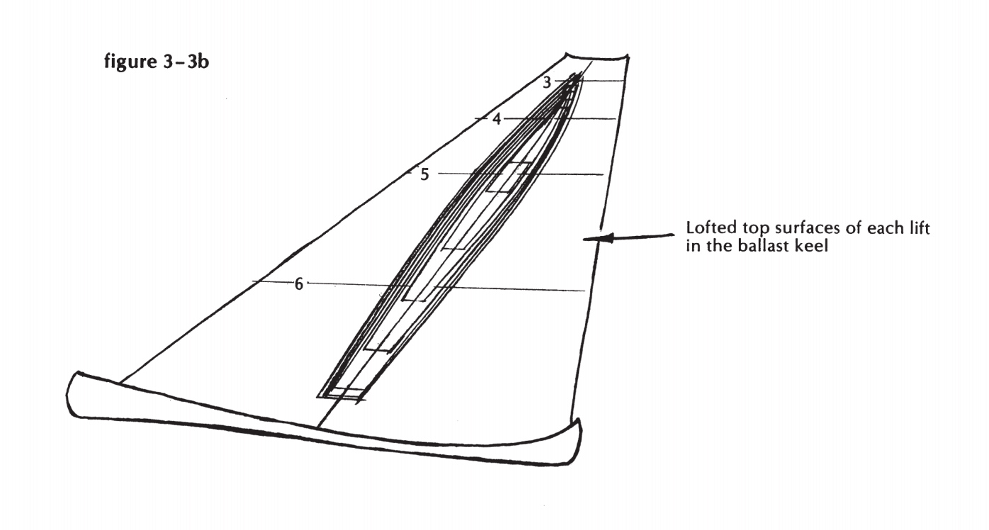
Figure 3-3b
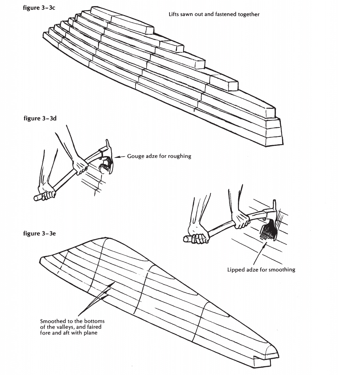
Figure 3-3c, Figure 3-3d, Figure 3-3e
The lift model method
Instead, suppose we build this pattern as if it were a lift model-using layers of 2-inch plank, sawn to shape, pinned together, and faired off with adze and plane, as shown in Figure 3-3. This makes much more sense. This method will eat up a lot of good pine plank, and will require some additional lofting and much hand planing, but it’s simple, foolproof, and entire satisfactory (and the molders in the foundry can ram the pattern to their hearts’ content and never dent it a bit).
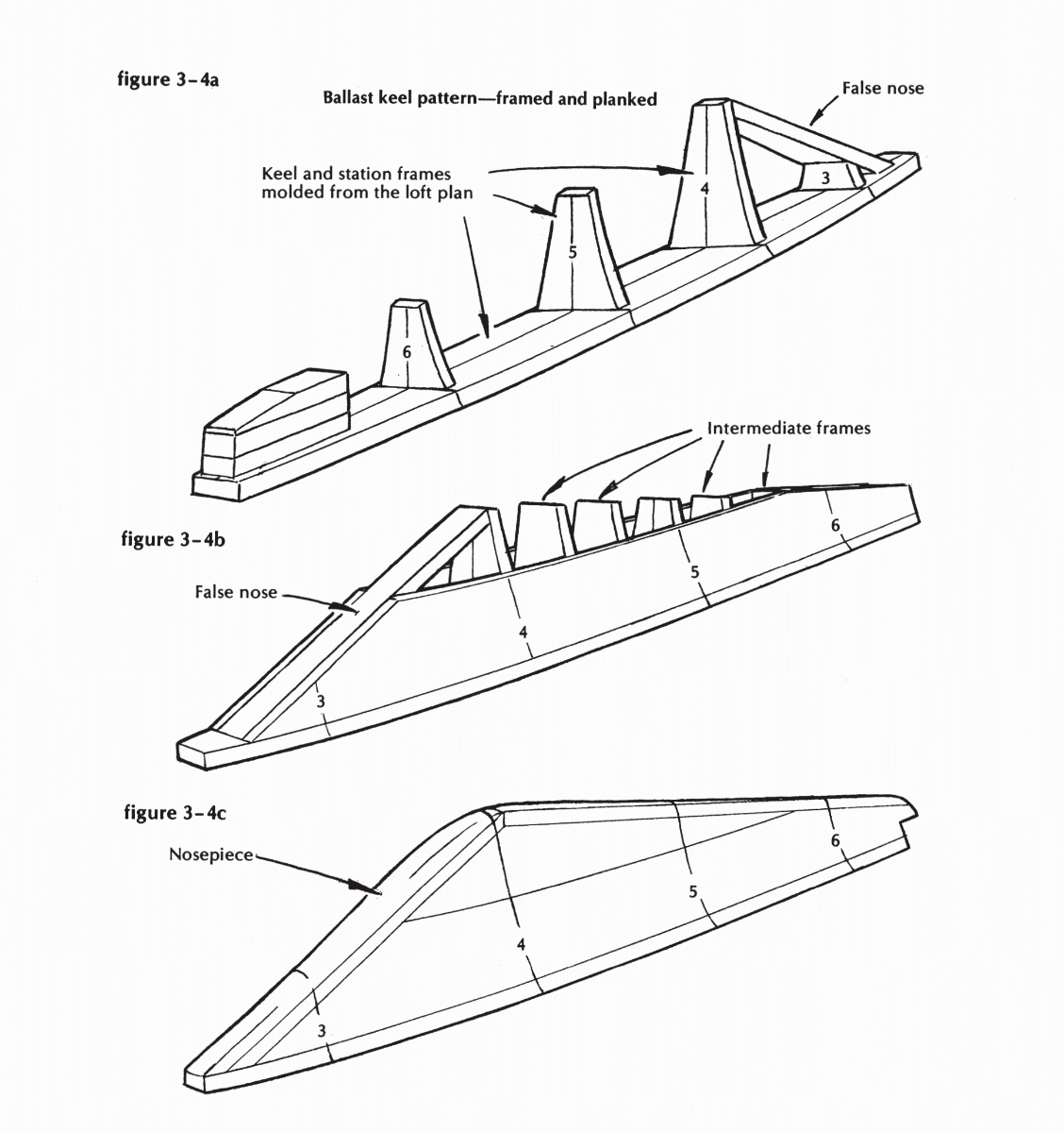
Figure 3-4a, Figure 3-4b, Figure 3-4c
Back to the lines on the floor, then. Tack down a fresh piece of building paper-longer than the pattern you’re going to make, clear of the casting in the body plan, and parallel to the keel. Draw a centerline on this strip, exactly parallel to the top of the casting (Figure 3-3a). Mark this line where each station ordinate crosses it,-and at each end. Draw a line square across at each mark. Now lay off and pencil in the half-siding of the rabbet line in the plan view, and extend it all the way to the after face of the sternpost. You will not use this rabbet line in shaping the pattern, but it will serve as a guide to the lines you are about to develop inside it. Each one of these lines will represent the top surface of one of the lifts that will make up the pattern.
Go back to the body plan; intersect each station line I½ inches below the rabbet height at that station; take these widths out from the centerline; then lay down this line in plan view, as you just laid down the rabbet line. This line you have just drawn, of course, represents the top of the casting, and the top of such deadwood as may be used to continue the shape of the casting all the way aft. Now go through this process again to get the shape of the top of the second slice down from the first exactly the thickness of the stock you are using. (This thickness is purely arbitrary and depends solely on what you can get. Probably 1 7/s-inch thickness is the likeliest.)
You will, of course, note that the forward and after ends of each lift are determined by their intersections with the profile, except at the top of the forward end of the pattern, where the lifts are cut off square to butt against a small fairing piece. All lifts will have the same half-siding at the line of the rudder stock, even as their points of intersection move progressively forward (Figure 3-3b).
Continue this laying down, then, until the ninth, tenth, or whatever slice appears as a short little pad at the toe of the profile, and prepare to reproduce all these flats, double, in wood. You can use the nailhead walk-about system for printing the half-width and centerline, and develop the other half with measurements and a batten on the other side of the centerline. Be sure that the centerlines are exactly right, and mark at least one station on each lift so that you can locate them in their proper fore-and-aft positions.
Saw the lifts out right to the line. Pile them up, upside down, holding each lift to the one below it with glue and plenty of 3-inch number 12 screws. The pattern should now look like Figure 3-3c-corrugated, but showing promise. All that remains to be done is to work the pattern down to the lines until it is perfectly fair and smooth, when it will be ready for core prints and three coats of shellac.
Right now, with this rough thing confronting you, you need a shipwright’s lipped adze and some confidence in the use of it. If you can’t find an old adze, complete with handle, order a new one from your ship chandler and fit a handle yourself. (I know of one book on boatbuilding that discourages any amateur’s hopes of mastering this tool; but the text’s accompanying drawing, depicting this strange and wonderful instrument, shows the handle in backward. If the author attempted to use it like that, he comes by his pessimism naturally.) Actually, a good adze is one of the easiest of all tools to use; it is precise, powerful, fast, and far safer to use than a hammer. So get one-or three or four assorted sizes and shapes, if you can; Figure 3-3d shows how a gouge adze is used for roughing, and a lipped adze for smoothing and practice with it for a few minutes. Sit down, holding the end of the handle so it is anchored in your left hand against your tummy. Lift the handle with your right hand and chop down gently. Cut across the grain, seldom with it. Slide your left hand down your front as the cut moves down the timber.
But shun the broadaxe, my son, because that is a tool that’s hard to master. I can still recall the dismay I felt, at the age of six years, when my father gave me my first real chopping axe and told me that you have to start really young if you’re ever going to be a good axeman. A fine thing to spring on me at that late date! There I was, practically grown up, and just starting to learn. And I was right. I never did become a good axeman, but I can cut out wooden gears for an alarm clock with an adze. So can you, by the time you’ve got that pattern roughed off to the hand-plane stage.
The frame-and-plank method
I promised three ways to make this pattern. The third way is to build it like a boat-framed and planked, as in Figure 3-4.
The top of the pattern should be cut from 2-inch pine plank, just as you laid out and cut the first lift in the above process. Mark the centerline and stations on its under face, and lay it upside down on at least three horses. This represents your keel, so be sure it’s straight. Clamp the plank to the horses so it will stay that way from now on.
Go to the body plan, and there lay out the shapes of the stations in way of the ballast. From these you will make up solid bulkheads, cut to shape from heavy pine boards. Each one will be 2 inches short at the top and bottom, and 7/s inch scant in width on each side. The top edge of each will be cut to the angle of the drag (downward slope aft) of the keel. Set these upon the upside-down top so they are centered exactly, toe-nailed in place, and braced at the correct angle.
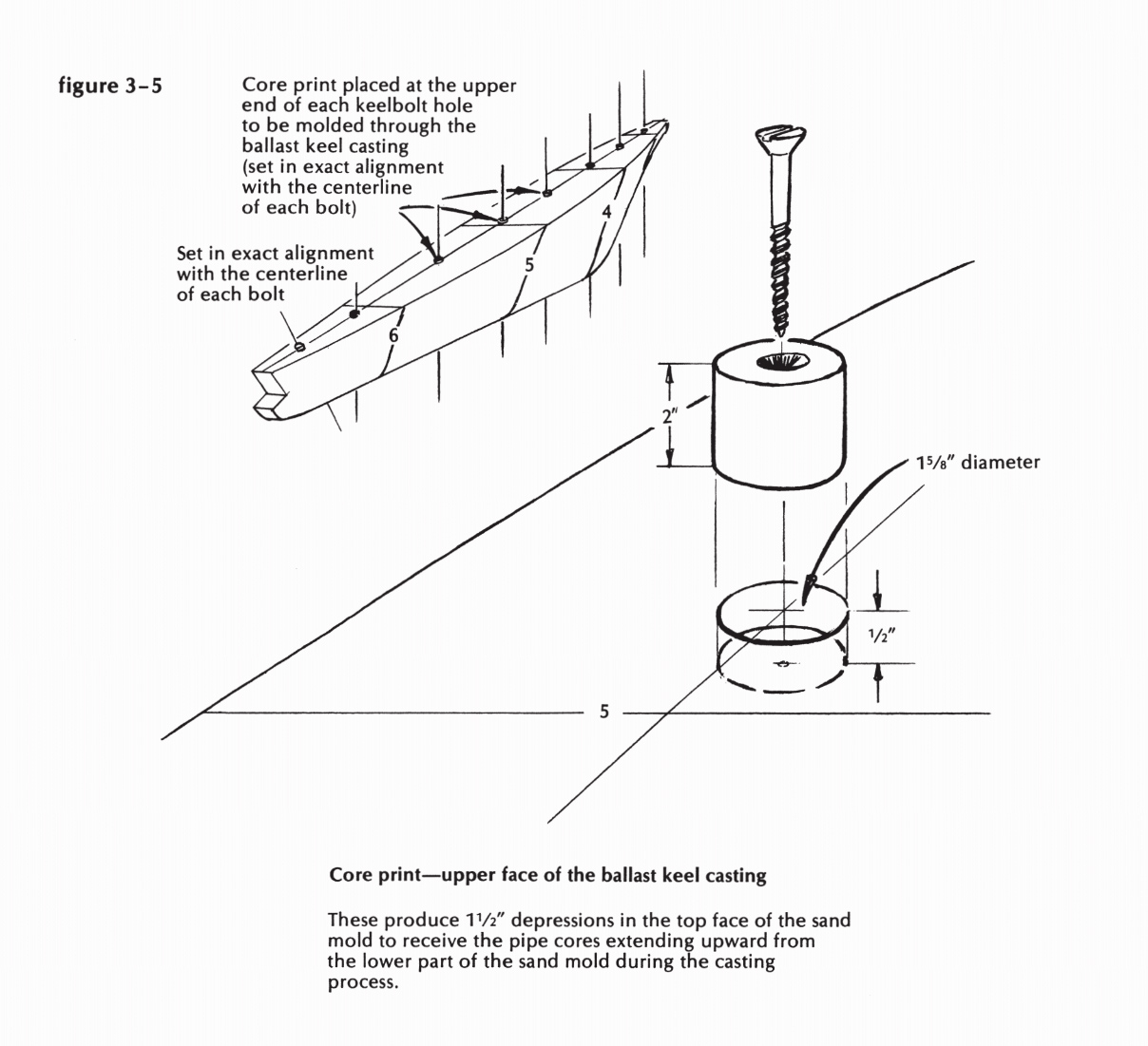
Figure 3-5
Now fit, brace, and fasten a false nose, as shown in Figure 3-4a, so it is roughly parallel with the forward profile of the ballast casting and about 6 inches aft of it. You must cut off the number 3 bulkhead to allow the passage of this false nose from the underside of the plank top to the straight line determined by the bottoms of the bulkheads on stations number 4 and number 5. (“Bottom” here means, of course, the true lower ends, which are at the moment facing upward as this pattern is being assembled.) This false nosepiece will be straight sided, and its taper determined by widths at its intersections with the number 3 bulkhead and the plank that forms the inverted backbone. Allowance must be made, of course, for the beveling of that plank, as shown on station number 2 of the body plan, and for the 7/s-inch boards that will be bent around, outside the frames and the nosepiece, to constitute the side planking of this pattern (Figure 3-4b).
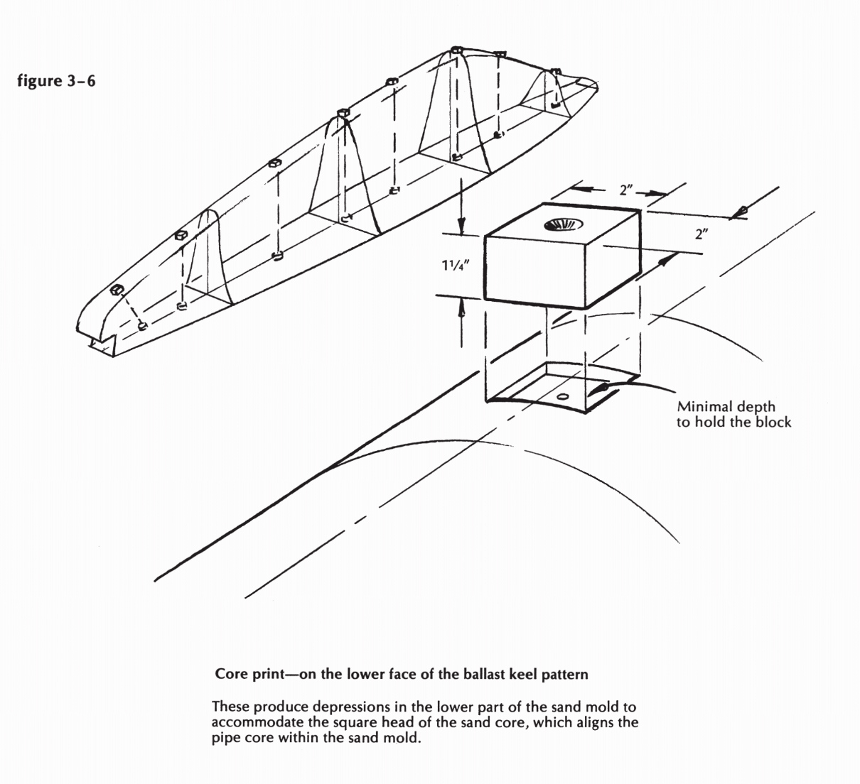
Figure 3-6
Before planking, however, you must fit intermediate frames a foot apart, between the station frames already in place (Figure 3-4b). These either can stand plumb to the backbone, or be raked to match the station frames. To get their shapes, you will, of course, work to two curves, determined by battens bent around the station frames, top and bottom. When you fasten them in place, align their center marks exactly to a straightedge tacked to the lower ends of the station bulkheads.
Now to plank the sides of this pattern: Start with a straightedged board, about 10 inches wide and 16 feet long, and clamp it to the number 4 bulkhead, with its lower edge up 3 to 4 inches from the backbone. Do the same on the other side with an identical board. Pull the forward ends together until you can clamp across and squeeze the false nose between them, with their lower forward corners almost touching the backbone. Go aft, arid pull the after ends together. The lower after corners should be just clear of the backbone, if your guess at
number 4 was right. This is, of course, too much to expect; so loosen the clamps at number 4, and move the clamped-together after ends up or down as may be necessary.
The purpose of all this double-action bending is to maintain equal pressure on both sides of the bulkheads, and thereby avoid pushing anything out of place. Now set your dividers as wide as –they will go, and scribe lines on these two boards exactly equidistant, at all points, from their final resting place on the backbone. Reverse the clamping-on process, and saw one out. Theoretically, the other one should be an identical twin; if a great discrepancy appears, try to find out where you went wrong.
Bevel the edges of the boards to fit against – the backbone; reclamp; mark for alterations in the fit, and for the cuts to be made flush with the forward face of the false nose and in the same plane as the bottom ends of the bulk-heads; take it all apart again, and alter and cut; reclamp, and fasten the boards to the bulkheads with 2-inch number 12 screws. The second boards, which will cover the remainder of the sides, go on next. Dress off the edges so they are exactly straight, right to the nosepiece, and fit to them the 2-inch plank, which will eventually be rounded off as the underside of the pattern. Cut its forward end flush and in line with the forward face of the nosepiece (Figure 3-4c).
Now build up the laminations of 2-inch plank, against the line of the false nosepiece, until you have enough material to make the shaped entering edge and toe of the pattern. When fastening these one to another, bear in mind the shaping that is to be done, and try to keep the screws clear of the danger areas. Use a drawknife, planes, and Stanley “Surform” wood rasps for this final shaping, getting the contours from plywood templates taken off the lines on the floor. Cut the after end to the exact line of the rudder stock, leaving the jog at the bottom as shown in the construction plan.
We still have to fit core prints and lifting eyes, make a core box for the bolt heads, and apply the final finish.
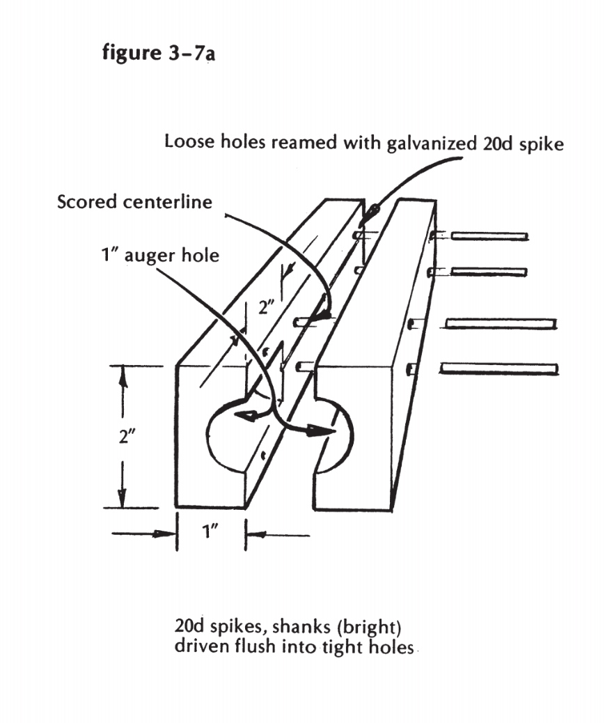
Figure 3-7a
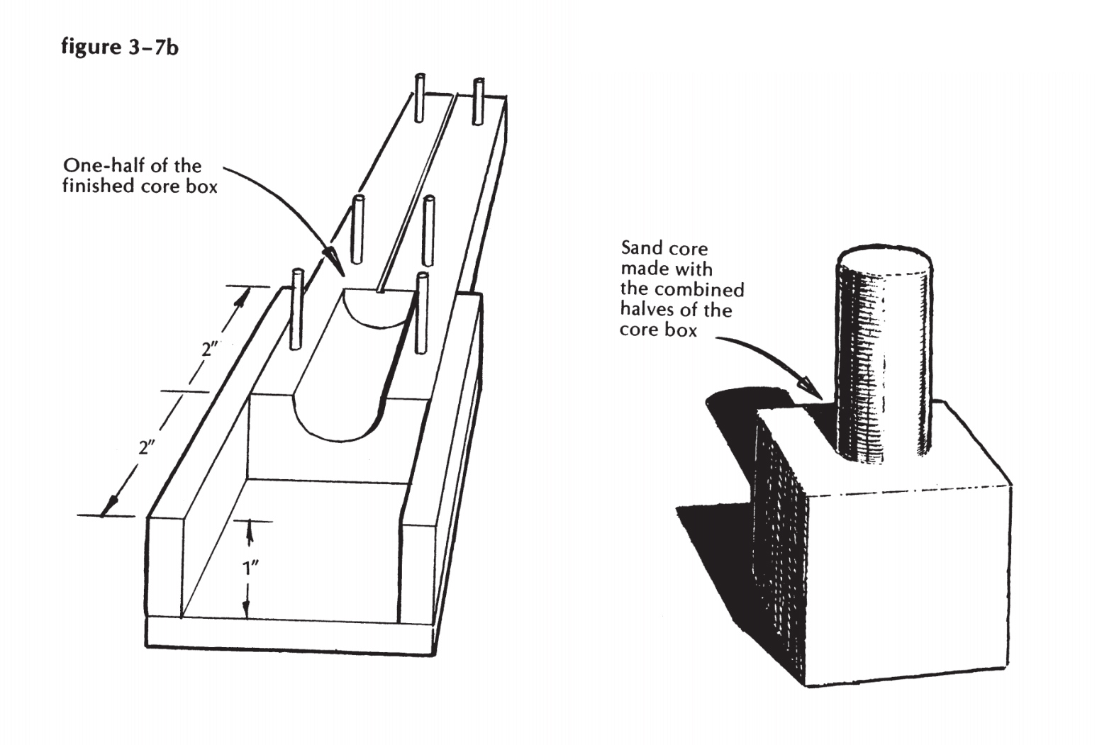
Figure 3-7b
Core prints and the core box
The core prints, of course, leave their marks in the two parts (“drag” and “cope”) of the sand mold that will be packed and rammed around this pattern at the foundry. (This explains the use of heavy scantlings for patterns. Foundrymen will not accept a pattern made of thin plywood, which will bulge inward under the pressure of the ramming.) These prints must match exactly the cores they are to accommodate-in this case, standard I-inch iron pipe, which measures l 5/16 inches outside diameter. For the top prints, therefore, plane out a 2-foot length of round stock, of this diameter, and cut it into 2-inch lengths.
Turn the monster right-side up, and lay out the locations of the bolts, as shown on the construction plan. (In this design, all bolts are on the centerline, and all but the aftermost one are square with the line of the keel.) Bore a shallow hole, about ½ inch deep and 15/16 inches diameter, at each mark; tap one of your round pegs into each pit, and fasten the peg with one 3-inch number 12 screw right down the middle (see Figure 3-5). There’s a good chance that the foundrymen will want these top prints out of the way during the first half of the molding, and the screw fastenings can be removed and later replaced without tearing anything up.
Now turn the pattern over and fit the bottom prints (Figure 3-6). These are blocks 2 inches square, to take the square cores which will form the pockets for the bolt heads, and, of course, center the lower ends of the pipes. They must stand up straight on the hillside-that is, their sides must be precisely parallel to the line of the bolts-and they must be carefully located, on the centerline, directly under the top prints. If you start with stock 11/4 inches thick, you will have enough wood left after fitting to the slopes.
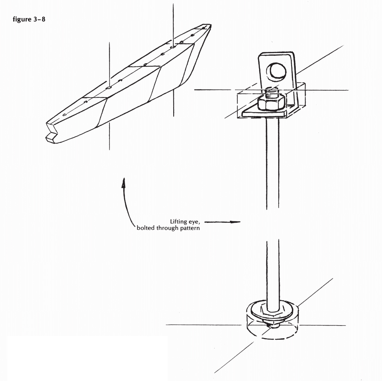
Figure 3-8
Now for the core box. Cut two pieces of pine exactly 1 by 2 inches, and about 8 inches long. Cut a groove about 1/16 inch deep by 1/s inch wide lengthwise down the center of one face of each piece. The easiest way to do this is on a table saw. Clamp the two pieces firmly together, groove to groove, with their edges matching exactly. Start the worm of a sharp I-inch wood auger in the double groove, and bore lengthwise (with the worm following the groove) a distance of 2 inches. Without disturbing the clamps, drill four /16-inch holes squarely through the two pieces to take slip-fit pins. Remove the clamps and spin a headless 20- penny galvanized spike through the pin holes in one of the two pieces. Cut lengths of plain 20-penny spikes for the pins, l ½ inches long, and drive them through the tight holes in the other piece (Figure 3-7a). Clamp the two pieces together and build a wall 4 inches high around the bored end, made up in two parts that separate on the same plane as the first two pieces.(See Figure 3-7b.) Take the core box apart, smooth all the inside surfaces, shellac, smooth some more, fill any crevices with beeswax, shellac again, and it’s done.
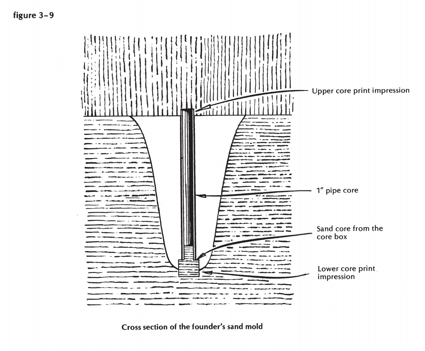
Figure 3-9
The foundryman will very likely snort and tell you he has a much better core box in the core room, but don’t let that bother you. If you hadn’t brought this one, you would have been treated to a demonstration of shocked pity for your ignorance. Quite seriously, though, if you don’t know much about this business, make friends with the foundry boss and watch the molders at work. Theirs is a fascinating art, and they’ll teach you some things you’ll need to know hereafter about patternmaking.
And, although they won’t expect it, they’ll be happy to see the pair of lifting eyes you are about to install in the top of your pattern. Remember, however, that if one of these eyes pulls out, after the crane has lifted the pattern clear, and the heavy end drops down and ruins a day’s work, you will wish you were not around to hear the comments. So install the eyes this way: Bore a 7/16-inch hole all the way through the pattern, from top to bottom; countersink at the bottom to take a washer and 3/sinch nuts; countersink at the top so that, with the top of a 3/s-inch threaded bolt just flush, there’ll be room to drop over it an upset shackle made of 1/s- by ¼-inch flat stock, with a hole drilled through its crown, and a full nut to hold it on (or buy a pair of 3/s-inch eye nuts). This assembly is pictured in Figure 3-8.
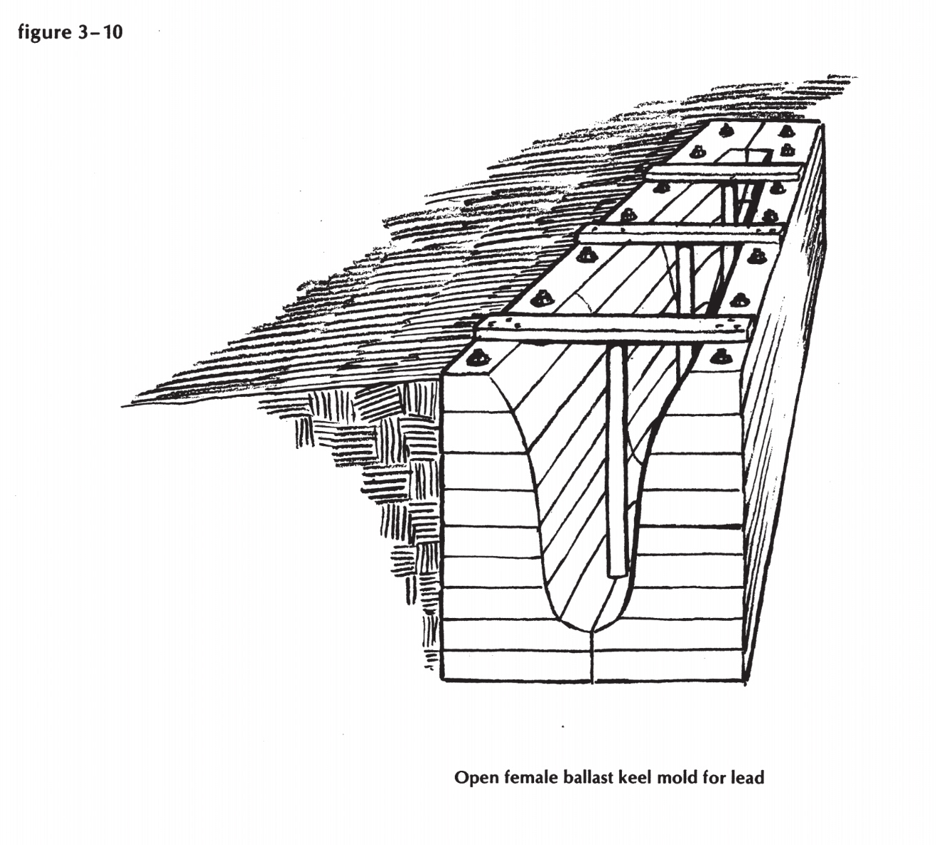
Figure 3-10
Female mold
A female mold, shaped, rounded, and flared, into which you can ladle your own bathtub lead, is built by the same contour system as described in the second method above, but reversed, with wooden walls, well-bolted top and bottom, surrounding the grand canyon, whose sides you will pare smooth with an adze, gouges, round-faced planes, and a disc sander. Make the mold in two halves, split vertically, so you can lay each on its side and really get at it for shaping-and so you can get it off the casting without breaking it to bits. Set the mold level, on a base that will support all those tons without subsiding or leaning. Use dry hardwood dowels for bolt-hole cores. Set the dowels in shallow holes at the lower end, held by well fastened cleats around the mold at the top (see Figure 3-10). Remember that the dowels will try very hard to float when the lead is poured. Paint the cores and the interior with something that will prevent charring of the wood. We once used ordinary waterglass, on somebody’s recommendation, and it certainly didn’t do any harm.
If I were doing the job, I’d pile and pack sand all around that mold, so that if it sprang a big leak, or a lot of small ones, I wouldn’t lose the whole damned shooting match.
Right now (never mind what I said at the beginning of this chapter), I’m beginning to think fondly of a good sailing dory with beach stones under the middle thwart. I heard somewhere that the pink ones are the heaviest.