Beginners Guide to Boat Batteries
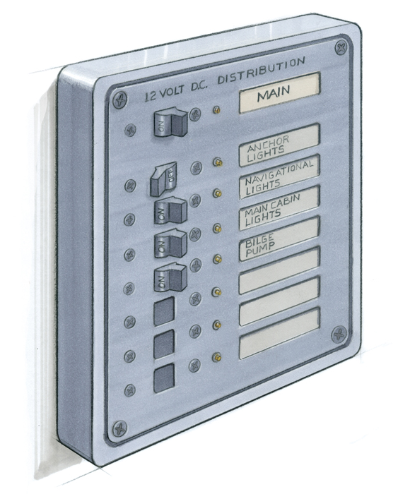
A proper onboard DC electrical system includes a distribution panel, which allows individual circuits to be switched off when not in use. The panel in this drawing includes three blank switch locations for the addition of circuits as needed.
The well-proven battery system design found on many recreational power- and sailboats has remained essentially unchanged for decades. As common as these arrangements are, however, their proper use can be a mystery to a beginning boater. And even for an experienced person, there are still many design and installation details that must be considered to make a battery bank and its systems reliable, seaworthy, and safe. There are also decisions to be made by the installer and user regarding redundancy, versatility, and compliance with commonly accepted guidelines, such as those established by the American Boat and Yacht Council (ABYC). While typically considered voluntary, such guidelines may be mandated by federal agencies in certain circumstances. Gasoline-powered boats, for instance, are required to meet a series of standards under the Code of Federal Regulations (CFR), many of which relate directly to batteries and other electrical components. Insurance companies may also insist upon compliance.
Batteries and their management are anything but a black art. Choose them carefully; ensure they are installed properly, safely, and in compliance with the appropriate guidelines; then make sure they are charged in a manner that suits their design, and your engine will always turn over and the cabin lights stay on.
Series or Parallel?
Two (or more) batteries that are connected in parallel will have double the capacity, or amperage, of a single battery, but the same voltage. A parallel bank is achieved when the positive posts are electrically connected, and the negative posts are electrically connected. A bank is said to be wired in series when the positive post of one battery is wired to the negative post of its neighbor. This yields no increase in capacity, but it doubles the voltage.
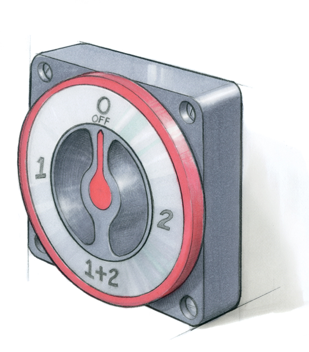
The conventional management of a two-battery-bank DC system involves the use of a four-position battery switch, which allows either or both banks to be used at a given time—or for the entire DC system to be switched off. Typically, one bank is designated as the “house” bank, and the other held in reserve for engine starting.
Battery Management
Traditionally, the builders and maintainers of boats using more than one battery connected them in such a way as to afford the user some degree of redundancy, and with good reason: It’s vitally important to be able to start the engine when you want to.
The most common battery installation involved two equally sized battery “banks” that were connected to the engine via a battery selector switch offering [battery]1, [battery] 2, BOTH [batteries combined in parallel] and [all batteries] OFF. The switch enabled the user to “manage” both the current leaving the batteries (for starting and other vessel loads) and the current that is sent to the batteries from the engine driven alternator.
Typically, for starting purposes, the skipper turns the multi-position switch to BOTH, which allows the engine’s starter to receive the maximum amount of cranking amperage by drawing from both banks. Even if the engine will start on a single bank, there’s some logic to this custom of supplying more current. If the starter labors because a single bank is weak or inadequate, or worse yet because the cabling is undersized or compromised, the drop in voltage may be excessive, which in turn causes an increase in current flow (cable size and current draw are inversely proportional for starter motor loads), and that in turn increases the heat that is generated within the starter. Over time this increased heat production and extended cranking can shorten the starter’s life.
Once the engine starts, the alternator begins charging. If the selector switch remains in the BOTH position, current from the alternator will be directed to both banks, charging them simultaneously. That’s straightforward enough, and it’s a system that has served thousands of boat owners well for many years. It’s the next step where events often go awry. Once the boat sets sail and the engine is switched off, or the boat reaches its destination, or drifts while fishing lines are put over the side, the boat’s electrical demand, often referred to as “house” loads—lights, VHF radio, fans, bilge pumps— will draw on both battery banks equally, if the skipper forgets to turn the selector switch to 1 or 2. Switching to 1 or 2 will keep the isolated battery in ready reserve for engine starting when it’s time to get underway. If the boat is idle for long—overnight, for instance—it’s all too easy to draw down both banks, making it impossible to start the engine without outside assistance.
There are methods of ensuring that a fully charged starting battery remains available at all times, and they don’t rely on the skipper’s memory. We’ll have a look at these on page 7, after we discuss battery types, basic charging protocols, and wiring.
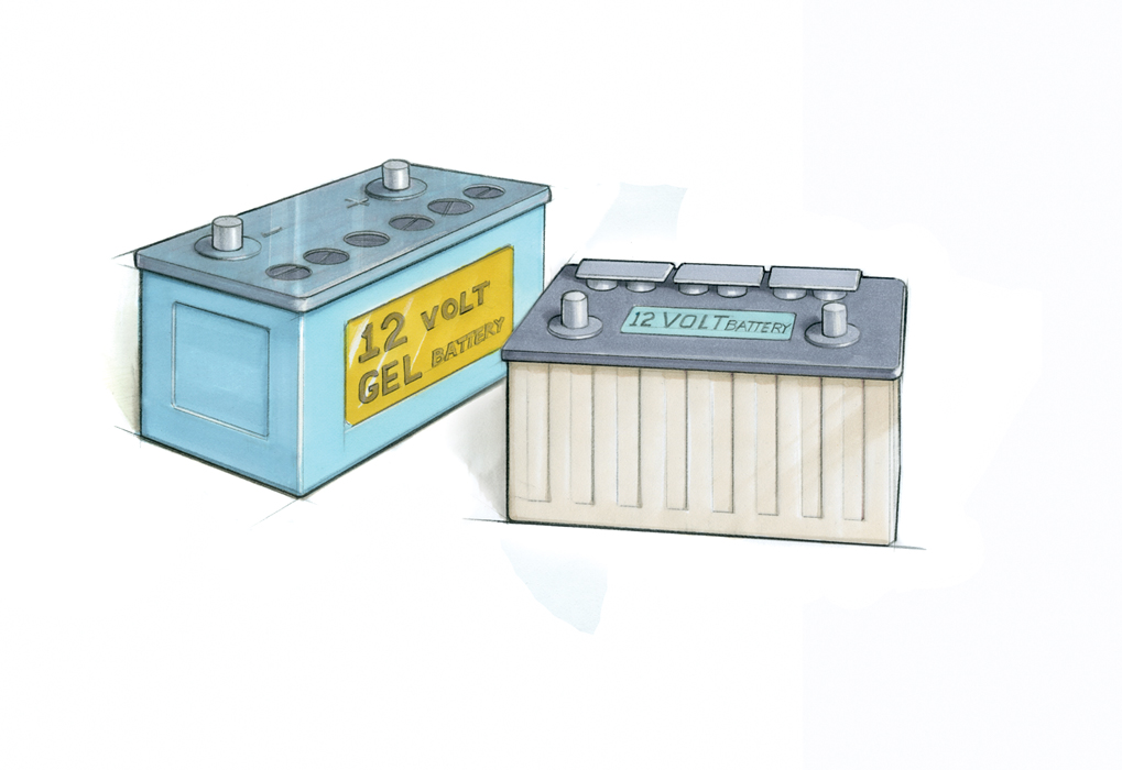
Most lead-acid batteries are immediately identifiable by their removable caps, which allow the addition of water when their electrolyte becomes depleted. Gel and AGM batteries have no such caps, and are similar to each other in appearance.
Types of Batteries
Flooded Batteries
Flooded Batteries are filled with a solution of sulfuric acid called free electrolyte. While some flooded batteries are “sealed,” or “maintenance-free,” the vast majority, and particularly those designed for marine applications, can be maintained by the addition of distilled water. These batteries can withstand repeated or chronic overcharging; when this occurs, they bubble or gas, sometimes vigorously, as they emit hydrogen. Gassing is normal, to an extent; it’s part of the chemical process that occurs in flooded lead-acid batteries and is the reason why they periodically require water (hydrogen being one of the constituents of water). Under normal circumstances, even if you can’t hear them doing it, flooded batteries emit hydrogen gas. While these batteries can endure overcharging, it should be avoided at all costs because it shortens battery life and makes frequent watering necessary, and the by product, hydrogen gas, is explosive.
Gel Batteries
Gel Batteries use the same chemistry (a sulfuric acid electrolyte) as a flooded battery but mix the electrolyte with a material called fumed silica— essentially, very pure sand dust—to create a gel. After the battery case has been filled with acid gel, it is sealed and slightly pressurized, usually to about 1.5 psi, which sometimes causes a case to bulge a bit though anything more than a slight bulge is abnormal. The pressure aids the reconstituting of water from hydrogen gas and oxygen generated during charging—the so-called recombinant process. This and the following style of battery are referred to as the sealed-valve-regulated lead-acid (SVRLA) type. If the battery is overcharged, the sealed valve will vent the resulting gases, a process that markedly shortens the battery’s life.
The primary strengths of a gel battery are that it requires no watering and recharges very quickly. This is because of the manner in which the electrolyte envelops the lead plates, and due to the pressure under which it operates. A gel battery can often be charged twice as quickly as a conventional flooded battery, provided it is connected to a properly regulated and sufficiently sized charge source. As one might expect, these batteries cost more than their conventional cousins, but if it’s quick recharging and low maintenance you seek, they may be worth considering.
Absorbed Glass Mat
The third battery type you are likely to encounter is an absorbed glass mat or AGM. Developed for and used by the telecommunications industry for decades, this battery is a relative newcomer to the recreational marine world. It embodies many of the attributes of the gel battery: it’s an SVRLA maintenance-free design, and it has a quick recharge time. Its acid is held in suspension using tightly packed fine glass fabric. Both AGM and gel batteries have very low self-discharge rates. That is, if left with no load and no charge source, they tend to stay fully charged almost indefinitely. The AGM will accept a charge even more quickly than the gel, twice as fast in most cases, provided it’s connected to a large enough and properly regulated charge source.
When it comes to battery-type selection, when comparing like quality, you often do get what you pay for. Flooded batteries tend to be less expensive than the gel and AGM types, with AGMs being the most expensive and now the most popular among SVRLAs.
A final thought on battery types: SVRLA batteries require a three-stage charging regimen, with the stages (typically called “bulk,” “acceptance,” and “float”) having charge voltages that differ from the voltage typically supplied to conventional flooded batteries. This charge comes from a proprietary alternator-regulator package or shorepower charger. Failure to use these chargers will lead to premature battery failure.
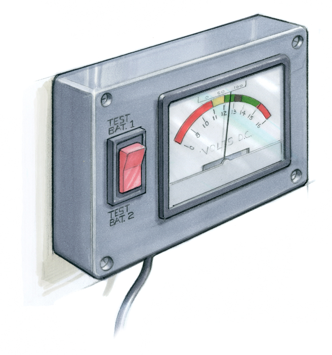
A fully charged battery that has rested for six hours will measure between 12.6 and 12.8 volts. The meter should read above 13.8 volts when the battery is being charged.
Charge Protocols
With few exceptions, most alternators that are standard equipment on marine engines are nearly identical to those used in automotive applications through the 1970s, with one important exception: Alternators, starters, ignition systems, and other electrical components used in the engine compartments of gasoline-powered boats must be ignition-proof. That is, they are designed to prevent the accidental ignition of flammable vapors that may inadvertently make their way into an engine compartment. For this reason, one should never substitute an automotive alternator or starter for the marine version; the higher price of the latter is justified. Such substitutions are dangerous and a violation of federal law. Diesel engine applications are exempt from this requirement.
The typical marine alternator is quite simple, and is designed primarily to replace the energy expended by the battery during the starting process. This energy is often much less than most users believe, and it’s often replaced in just a few minutes of running time. After that point, the alternator is available to supply house loads. If the house loads exceed the often-modest output of stock alternators, the batteries will make up the difference—at least for a time, until they are depleted. A user must thus be mindful of the rate of power consumption and power production.
A voltmeter can monitor the basic condition of the batteries as well as the output of the alternator, but this ubiquitous device has its limitations. A fully charged and “rested” (rested is defined as a battery that is subject to no loads or charge sources for six hours or more) battery will be between 12.6 and 12.8 volts, while a 50-percentdischarged, rested battery will measure between 12.3 and 12.4 volts. As you can see, there is a scant difference between the two readings, and accurate measurement requires resting the battery, which typically isn’t practical. Incidentally, none of the aforementioned battery types should be discharged beyond 50 percent of their capacity, because routinely doing so will diminish the amount of energy they will provide over their lifetime. The voltmeter is slightly more useful for measuring rate of charge: While it’s an oversimplification, any reading over approximately 13.8 volts can be considered as “charging.”
Stock alternators utilize a regulator, which monitors and controls the rate of output from the alternator. The regulator is nearly always built into or screwed onto the alternator itself, making it a complete charging package. To a certain extent, the batteries’ state of charge controls the regulator’s signals to the alternator. When the battery is depleted, or if house loads are high, the regulator will command the alternator to produce more current. It’s important to remember that standard regulators have two primary missions: recharge the starting battery, and supply modest house loads. If called on to do more than this, their performance will nearly always be inadequate.

A bank of batteries should be wired in such a way that current is drawn across the bank—that is, the positive lead exits a battery at one end of the bank, while the negative lead exits at the opposite end.
Some Wiring Wisdom
Regardless of how large or small a battery bank may be or what it’s called upon to do, two wiring rules must be followed. First, all wiring should be installed in accordance with ABYC or, where mandated, CFR guidelines to ensure safety. Among the most important of these is the overcurrent protection mandate, which calls for a fuse or circuit breaker in every wire, save one, that leaves any battery’s positive post. This overcurrent protection, often abbreviated as OCP, must be installed within 7″ of the battery terminal. This distance may be increased to 72″ if the wire is “sheathed.” Sheathing can include anything from proprietary wiring loom to conduit; a wiring loom should meet ABYC guidelines for the protection it affords the wire as well as for fire resistance. Therefore, if you can follow any wire from any battery positive terminal for more than 7″ (or 72″ with sheathing) without bumping into a fuse or circuit breaker, the installation does not meet this important guideline, and the oversight should be corrected without delay. Any wire between the OCP and the battery is essentially unprotected and is therefore a fire risk in the event of a short circuit.
The one exception to the OCP rule is the cabling used for starting circuits. Any cable used, or that can be used via paralleling switches, to supply current to a starter is exempt from the OCP requirement. Because of that exemption, such cabling must be routed with extreme care to prevent chafe or short-circuiting. Other than the one that connects to the starter post, positive cables must not make contact with any part of an engine or its mounts.
Battery banks, depending on the number of individual batteries included in the bank, should be wired in such a way as to draw current across the bank. For example, the positive and negative cables connected to three group 31 batteries wired together in parallel, should attach at opposite ends of the bank, to ensure all batteries are cycled evenly. If the cables are attached to a single battery at the electrical end of the bank, that battery often bears the brunt of the discharge and it is likely to become depleted before its brethren, making for an undesirable imbalance within the bank.
Note: Battery case size is denoted by “group” number; group 31 is slightly larger than an automotive or light-truck-sized battery. Automotive-size batteries are typically group 24.
A final note on wiring: Bigger is nearly always better. That’s an oversimplification, but where electrical current is concerned, large cables present lower resistance, which means more of the energy gets to where it’s going rather than being lost as resistance-generated heat. Therefore, closely follow engine-manufacturer guidelines for starter cable size and length, and rely on standard voltage drop guidelines (available in a variety of books as well as from ABYC) when making charging and starting system connections. Voltage drop should never exceed 10 percent, while 3 percent is preferred, particularly for voltage-sensitive equipment such as bilge pumps, navigation lights, and communication gear.
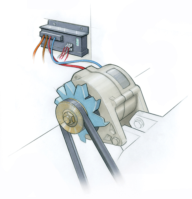
A high-output alternator charging a Gel or AGM battery requires a regulator that can be programmed to optimally charge a particular battery type.
Advanced Charging Protocols
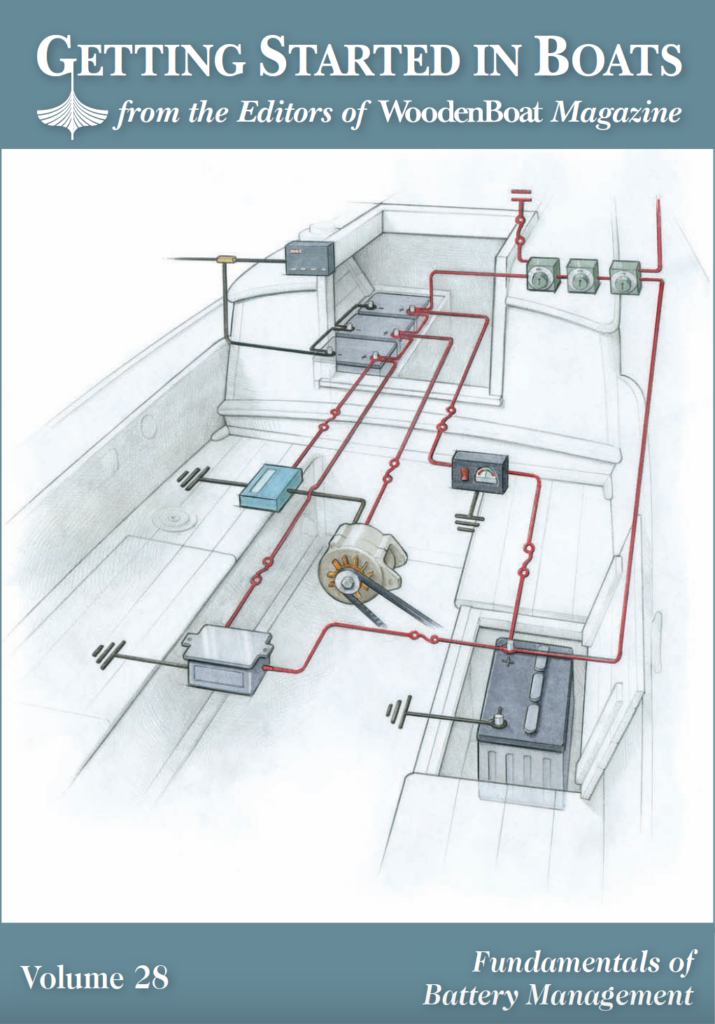
Up to this point, we’ve considered a charging system using only the basic alternator supplied with most engines—a system that has worked well and continues to remain effective for many owners and operators. However, there are several improvements that can be implemented to increase efficiency of this system, make it more user-friendly, and still keep it reliable. All of the suggestions that follow are tried and proven designs that I’ve personally used aboard hundreds of boats, and they’re illustrated on the cover of this supplement.
While the traditional use of two identical batteries or battery banks using a multi-position, 1, 2, BOTH, OFF power distribution switch may be familiar to many, there is room for improvement. Studies show that using a single battery bank for house loads and cycling it through approximately 50 percent discharge will yield the greatest amount of amp-hours over the life of the battery. This bank also becomes the primary recipient of charge current from any source—alternator, shore-power charger, or solar panels.
Note: An amp-hour is a measure of battery capacity. One amp-hour being equal to a one-amp load operating for one hour. Think of it as the equivalent to gallons of fuel in your tank.
In order to ensure the engine can be started under any circumstances, it should be given its own dedicated battery or battery bank. This bank, usually smaller than the house bank, remains electrically separate from the house bank under all but emergency starting needs, so there’s no danger of waking up to a dead starting battery.
Instead of the 1, 2, BOTH, OFF switch, the improved arrangement uses three simpler ON-OFF switches, one for each battery bank and another between the two that is used to manually parallel the banks if the engine-starting battery fails. Proper wiring of this so-called “parallel” switch is important: It should be connected to allow either the starting or house battery switch to be turned off while still allowing paralleled voltage to flow to that switch’s loads (in electrician-speak, the connections are made to the “load” side of the house or starting switch). With such an arrangement the user can essentially take a defective, damaged, or internally shorted battery off line entirely while allowing its loads to be supplied by the paralleled battery.
For those using SVRLA batteries or for those wishing to supply their flooded batteries with the quickest and “healthiest” possible charge, an aftermarket, high-output alternator and external regulator kit become a necessity. Because SVRLA batteries require a charge that’s significantly different from conventional flooded batteries, this kit must be part of an upgrade to this battery style.
High-output alternator/regulator installations offer a variety of benefits for any battery type. These include increased sustained output, typically on the order of 100 or more amps; a three-step charging regimen that provides the quickest possible charge; and a temperature-compensated charge profile (warm batteries cannot be charged as quickly as cool batteries). Most aftermarket regulator kits can be programmed to charge a variety of different types and even brands of batteries. Consider this setup as granola and fresh vegetables for your batteries; it gives them the best charge possible.
If all the output from the alternator goes to the house bank, how, you might ask, does the starting battery get charged? One of two approaches may be used. The simplest involves the use of an isolator that essentially splits the output of the alternator, sending it to both the house and starting banks simultaneously. Because the starting bank is likely to be nearly fully charged and thus have a higher internal resistance, it will accept less of the output, allowing the bulk to go to the house bank. An alternative, and one I prefer, is to use one of the many proprietary starting battery charge devices that more intelligently shunt a small amount of charge to the starting battery. Some of these devices include temperature monitoring and compensation, which comes at a higher, but I believe worthwhile, price. Generally speaking, however, they will send a limited or regulated amount of charge current to the starting battery
Finally, the next-generation charge system requires next-generation monitoring, something a bit more sophisticated than a voltmeter. Amp-hour meters are significantly more useful than voltmeters in that they accurately measure the amount of energy used from, or remaining in, the house battery bank. Armed with that information, you can make an informed decision as to when it’s time to recharge.
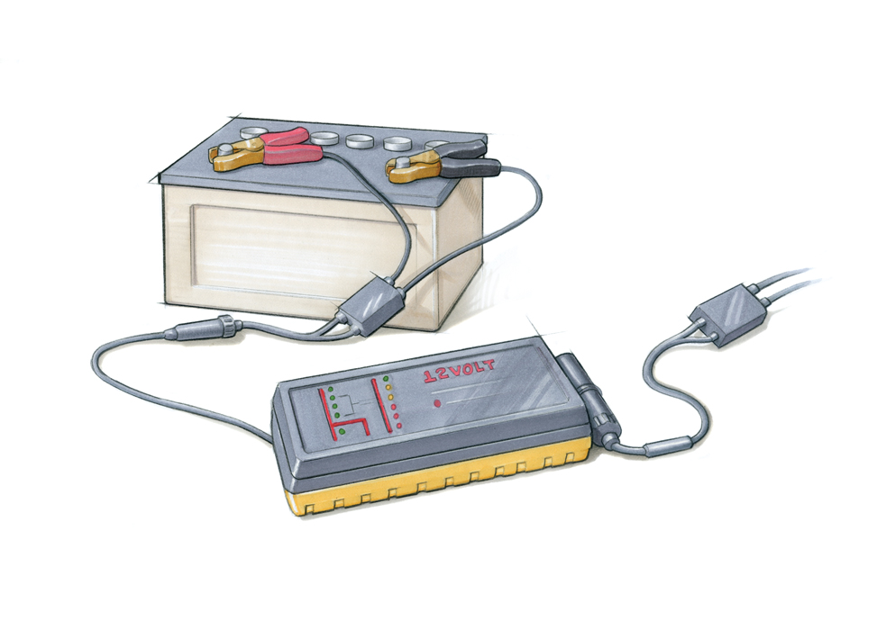
Because a fully charged battery will not freeze, it’s best to leave batteries aboard in the winter months, and to keep them charged.
Off-Season Battery Storage
One of the fall rituals observed in a boatyard I worked in many years ago involved the removal of batteries from most of the boats that were wintering over. The batteries were placed in a heated shed and charged periodically, the logic being that because batteries always seem to have less power when cold, keeping them warm during the winter must be better for them. In hindsight, this was a less-than-ideal approach. The potential for damage to the battery as well as the boat, not to mention the backs of the poor souls doing the lifting, was significant, and as it happens, flooded and SVRLA batteries endure extreme cold just fine. In fact, the reason a battery has less oomph when it’s cold is because the falling thermometer is slowing down the battery’s internal chemistry, sending it into a sort of
hibernation, which is actually desirable when it’s not being used, with one provision: The battery must remain charged. A fully charged battery won’t freeze, while a dead or weak one will. If a battery is allowed to freeze, it will almost certainly suffer internal, and possibly external, damage that may result in a fire or even an explosion should a charge be applied—either while still frozen or after the battery thaws out. The axiom here is: Leave the battery aboard, make certain all its loads are disconnected, and charge it periodically—once a month is probably enough for flooded batteries, and every three months for SVRLAs.
A former full-service yard manager and longtime technical writer, the author now works with boat builders, owners, and others in the industry as Steve D’Antonio Marine Consulting, Inc.

