Getting Started With Lofting
Lofting—enlarging a boat’s lines to full size—is an important part of boatbuilding. Having this skill opens the door to a wider variety of boats to build and to having better control over the construction process.
Some builders have a love-hate relationship with lofting, yet it pays us fourfold for our efforts. It allows us to make corrections (yes, even great designers can make a few mistakes), it helps us to better understand the designer’s plans, and it renders patterns from which we can build the boat. Additionally, it gives us some latitude in making changes, such as sweetening the sheerline or adding a bit more rake to the transom.
I have chosen the Asa Thomson skiff for my subject. This article will cover the basic steps required to loft this simple flat-bottomed boat. The goal is to replicate, at full size, enough of the lines shown on the drawing so you can build the four station molds, the stem, and the transom.
Some very fine builders have tackled the subject of lofting. Among them are Greg Rössel in his two-part article, “Lofting Demystified” (WoodenBoat Nos. 110 and 111) and Sam Manning in his article, “Some Thoughts on Lofting” (WoodenBoat No. 11). Both are rich in information but feature round-bottomed boats, which are more complex than the flat-bottomed skiff we will discuss here. I will reference these—and other works—as this article is intended as a primer to those writings and as a starting point for the first-time loftsman.
Plan Conventions and Quirks
While most designers try to stick with certain conventions, sometimes it makes sense to break a rule or two—and sometimes rules are broken for no apparent reason. Here are a few of the conventions for drawn plans:
- In the profile view, the bow is usually to the right.
- Stations are usually equal divisions along the designed waterline, beginning from the right, or forward, end of the boat, and proceeding toward the left.
- The body plan is composed of a half-section drawn for each station, the forward part of the hull on one side of the centerline and the aft opposite, on the other.
- The standard layout is to show the profile view at the top, the body plan to the right of the profile, and the plan view aligned below the profile.
- Offsets (sets of numbers that define the boat’s shape) are most often read in feet, inches, and eighths of an inch. So, 1–2–3 means 1′ 2 3⁄8″.
- Plans can be drawn to either the inside or outside of the planking. If they are drawn to the outside of the planking, plank thickness must be deducted from the given dimensions when making the molds. If drawn to the inside of the planking, this extra step is not necessary.
To see deviations from these norms, we need look no further than the Asa Thomson skiff plan. First, her stations begin at the left (aft) end of the boat and proceed to the right. Next, her body plan is given in full section, rather than half section. In fact, two renderings are made, showing her forward sections and her aft sections separately. Finally, offsets for this plan read in feet, inches, and sixteenths of an inch.
These departures are not wrong. They are usually done for greater clarity. Since this is often a first-time builder’s project, these details are not excessive, and, diminutive boats like our skiff are best described with these more exacting offsets.
Every plan will display differences. Be sure to spend some hours studying your plan before jumping into the lofting process. It’s time well spent.
Lofting Tools and Supplies
- Loft floor (board), two 4′ x 8′ sheets of 1/4″ plywood with one “A” face
- Combination square
- Long straightedge, 4′ or more
- Batten, 3/4″ x 3/4″ x 14′, clear pine
- Pick-up sticks, 3/32″ x 1″ x 3′
- Chalkline, 16′ long
- Some 2″ box nails
- Light-duty hammer
- Colored pencils and pencil sharpener
- Erasers
- Knee pads
- Trammel points for swinging large radius arcs
Preparations and Procedures
Let’s look at the plan of the Asa Thomson skiff and see what we need to know to do our first lofting job. For convenience, this plan gives detailed construction information. The three main views are the profile, plan, and sections. The profile shows us the boat side-to in the upright position, the plan view shows the boat as if we were looking down on it, and the sections show the shape end-on, as if we sliced the boat like a loaf of bread.
These three views are related in a deliberate and important way. Notice that a given point on the boat, say the sheer at station No. 2, has two dimensions in the profile view: the fore-and-aft distance from station No. 0 and the height from the baseline to the designed waterline (DWL). The plan view shows the same fore-and-aft length as well as the width from the centerline. The sections show the width from the centerline (CL) and the height from the baseline. Notice that the same dimension appears in two different views and that this dimension must be the same in both views. As you are lofting any boat, it is absolutely required that you keep any dimension the same in all views in which it appears. This is known as keeping the lines dimensionally fair.
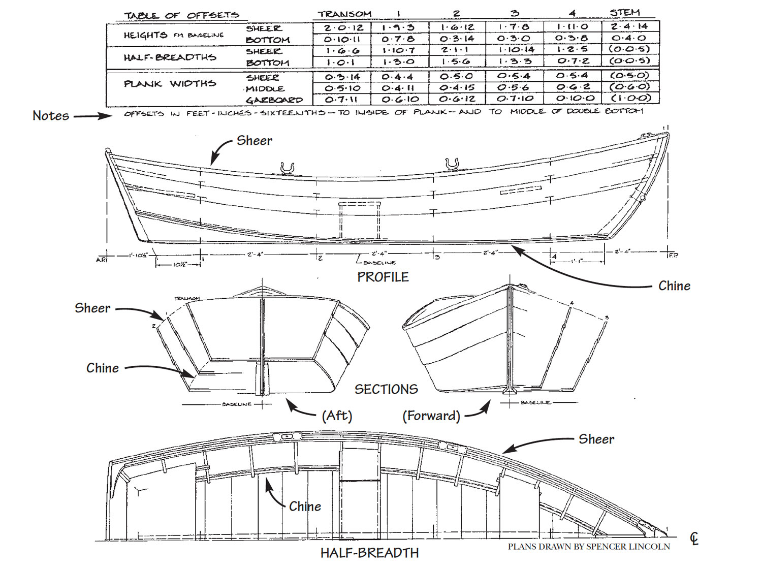
The two lines that we will be lofting are the sheer and chine (or, in this case, the bottom). These two lines define the outside shape of the skiff, and all other lines are derived from them. We will lay these two lines down at their full size on the loft floor using the dimensions given in the offset table.
Prepare the Lofting Floor
Your “loft floor” or “loft board” should be a couple of feet longer than the skiff and about one foot wider than its half-beam (half-width). Two 4′ x 8′ pieces of plywood laid end-to-end and fastened down to the shop floor will work well as a loft floor. Apply a few coats of shellac-based white or light gray primer to make your lines easier to see and to erase.
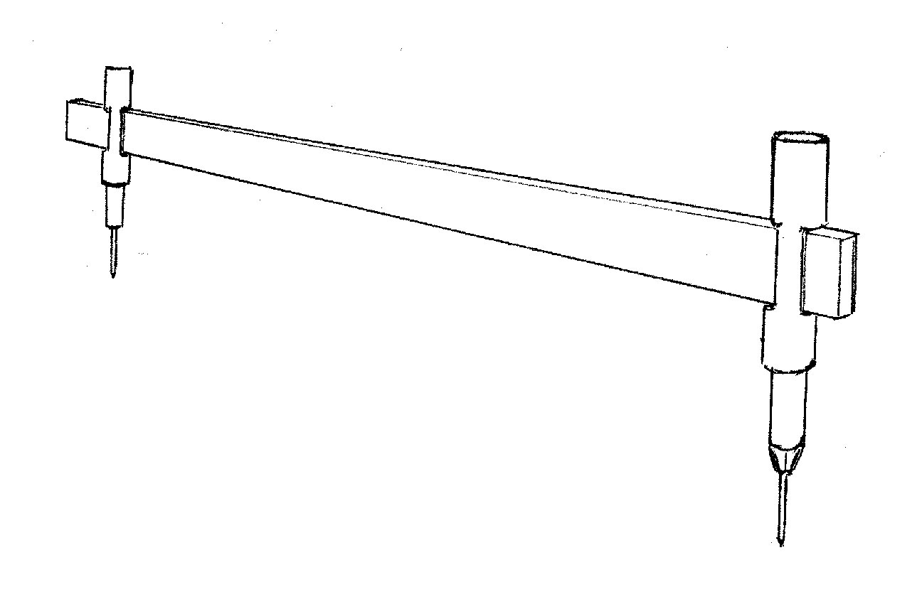
Trammels do the accurate work of full-sized layout in lofting. Their use as giant dividers helps avoid the mistakes made by misreading rulers.
Lofting will be easier, more accurate, and more fun if you team up with a buddy. It’s best to have one partner read an offset aloud and let the other repeat it aloud as a check before marking it on the loft board. Also, two people can set down the batten much more easily than one. Wear knee pads and be sure to remove your shoes!
Alternatives to the Lofting Floor
Lofting was traditionally done on the floor of a boatshop’s loft. However, if you would rather not crawl on the floor, there are alternatives. Greg Rössel suggests stiffening the back of the loft board and setting it on sawhorses. Sam Manning likes to hang his loft board on his wall. Both methods spare the back and knees.
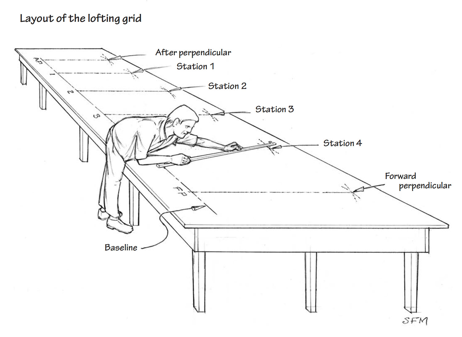
Laying Out the Lofting Grid
Lines are laid out on a right-angle grid. In order for your boat to be of the same dimensions and shape as the Asa Thomson skiff, your grid must be laid down accurately.
Starting the Grid Right
An inaccurate grid will cause errors that grow exponentially over the course of the project. Accuracy begins at the baseline. This line must be a continuous, straight line. Loftsmen of yore have used piano wire and turnbuckles for striking a baseline. Some loftsmen use a pair of ice picks to tension fishing line along their proposed line, and then set the head of a combination square so that it just kisses the line, make a series of marks along the line, and finally connect the dots. For our purposes, a chalkline, a long straightedge, and a steady hand will do nicely.
How to Lay Out the Lofting Grid
Start by snapping a chalkline about 6″ from the long edge of your plywood loft floor for its full length. Using a long straightedge, pencil in this line, which will serve as both the baseline in the profile view and the centerline (CL) in the plan view. This means that both the profile and plan views will be laid down on top of each other. It may seem a little confusing, but it saves a lot of space. Remember, in lofting, we enlarge the lines (i.e., the boat’s shape) for building purposes—we do not attempt to make enlarged, detailed construction drawings as found in the plans.
Once you have laid down an accurate baseline/centerline (CL), strike a perpendicular line about one-third of the way along the baseline. This will be station No. 2. To strike a perpendicular at station No. 2:
- Sweep an arc across the baseline with compass or trammel points set outward from station No. 2 at arbitrary radius “a”
- Sweep a second, longer arc of arbitrary radius “b” outward from the crossing points of “a.” For best accuracy, make “b” two or three-times longer than “a” (commensurate with keeping “b” on the loft floor
- Draw a line upward from 2 through the crossing of the “b” arcs. This line is perpendicular to the baseline
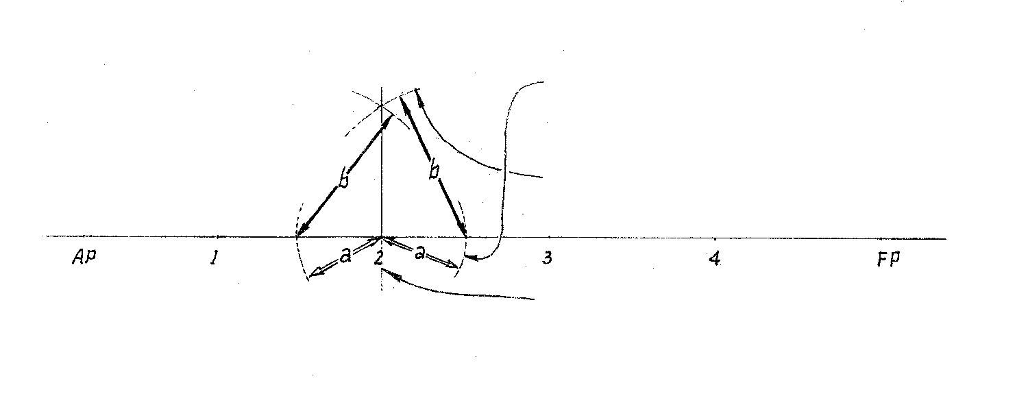
Then, measuring along the baseline from station No. 2, lay out the remaining stations, the aft perpendicular (AP), and the forward perpendicular (FP), and construct perpendiculars as done for station No. 2. You now have enough of a grid to start laying down your two curved lines, they being the sheer and the chine (bottom).
One of the most important tools you will use in lofting is the batten. Battens can be made in many sizes and from a variety of materials. Their function is to help you make a curved line that is fair. This means that the sweep it forms has no humps, bumps, kinks, or sudden changes in shape. A fair line is often referred to as being “eye-sweet.” Greg Rössel prefers battens that are made of long-grained wood such as spruce because of their uniform stiffness. He paints his black so they stand out against the loft floor. Some shops use polycarbonates for even better stiffness and durability. For our purposes, a batten made of clear pine about 3⁄4″ square and about 14′ long will work just fine.
Lofting the Sheer and Chine
Let’s begin by lofting the sheerline in the profile view. This is generally the most prominent visual line on any boat, and we want to make sure it has eyesweet fairness.
Lay down the heights, as given in the table of offsets, for the sheer for each station and the endpoints at the transom and stem, each time starting from the baseline. Remember that these offsets read in feet, inches, and sixteenths of an inch. So, the point that defines the height of the sheer at station No. 1 is 1–9–3—that is, 1′ 9 3⁄16″. Mark that point in a clear, 90-degree intersection with the station line. Continue for each station, as well as the ends of the sheer at the transom and stem.
Profile and half-breadth views are normally superimposed on the lofting grid to save space and minimize error by measuring outward from (“offset” from) the same centerline/baseline and the station perpendiculars. The offset table corrals the governing measurements. The body plan, developed within these full-sized superimposed views, is usually laid out upon a scrive board easily moved to the construction site.
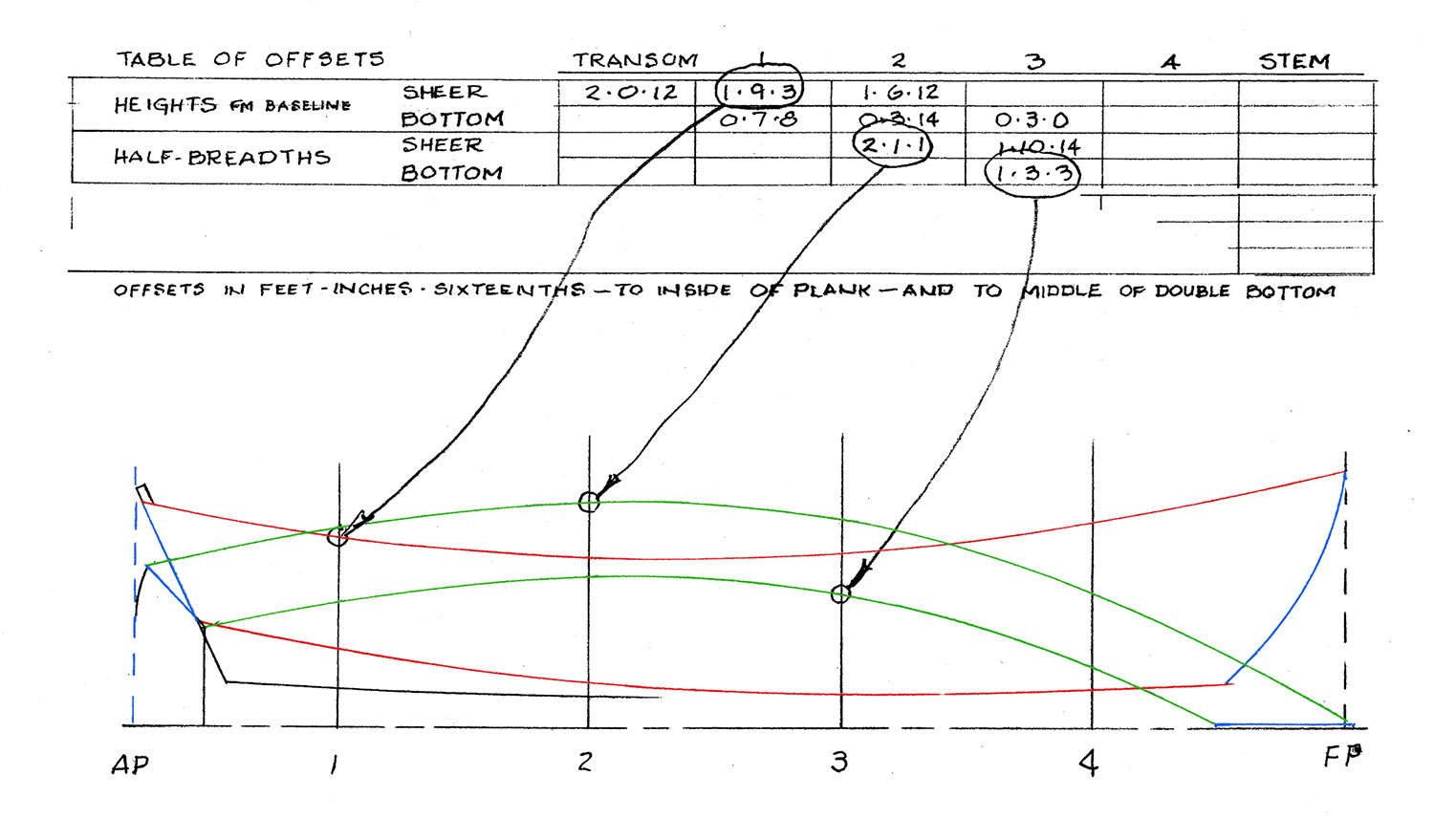
Next, lay the batten on the floor and, using 2″ box nails, set the batten at station No. 2. To do this, drive a nail into the plywood loft floor, next to the batten on the inside of the curve, as if giving it a place to lean. Don’t drive nails through the batten. Position the batten so the sheerline points can be seen on its convex (tensioned) side. This will help you see the batten and line when you later check for fairness. Next, fasten the batten in a similar fashion at the remaining points.
Letting the batten run straight beyond the two endpoints can introduce some unfairness. To prevent this, continue the curve of the batten beyond the endpoints of the boat and fasten it about 18″ from them.
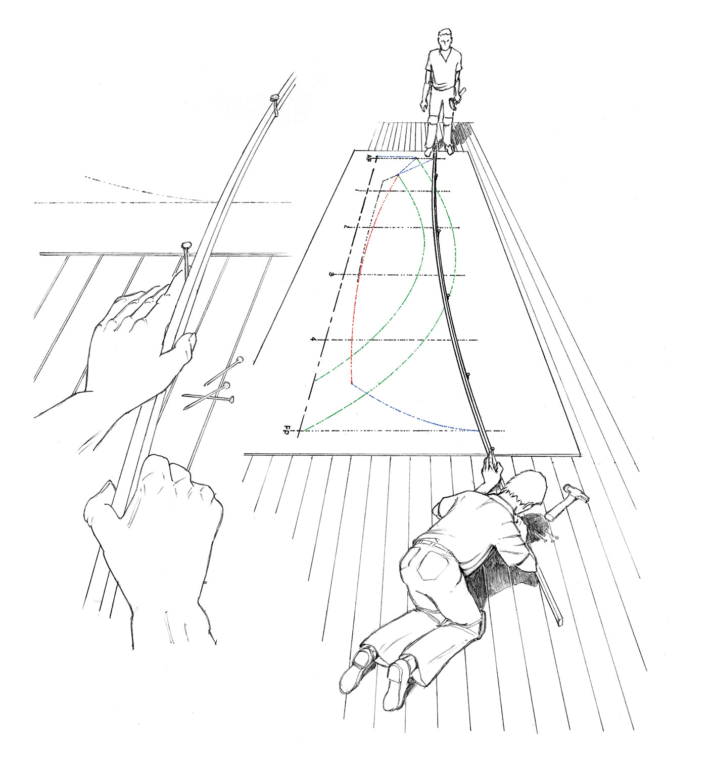
Now comes the eye-sweet fairing. Get your eye right down on the floor and sight along the convex side of the batten, then stand back and sight along the batten again (see cover illustration). Is it smooth all the way along? If not, release a nail where you think the unfairness is and see what the batten does. If it moves, the line was probably unfair at that spot. If not, refasten it and try the adjacent station. A good trick is to release each nail in order (except for the end ones), see if the batten moves, then refasten it.
It is common to see some small movement at some stations, say between 1⁄32″ and 1⁄8″. If the sweep of the batten is eye-sweet, trust it, as it wants to spring to a naturally fair curve. Then draw the line, pressing down on the batten between nails to keep it in position. I like to use colored pencils to help me discern the different views. Make sure that you clearly label each line with both its name and view (e.g., sheer–profile).
Repeat the process for the chine (bottom) in profile. Then, lay out the shape of the stem profile and transom using dimensions on the plan. In this case, the stem offsets aren’t shown on the plan (see illustration below). Because the transom slopes, its depth measurement is foreshortened and inaccurate in the half-breadth and the body plans. Its true shape must be laid out in a separate loft view with width and depth taken as shown here with the sketched dividers.
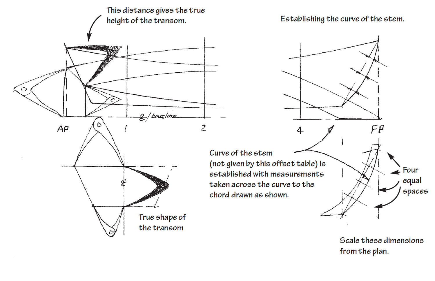
You are now ready to lay down the sheer and chine (bottom) in plan view. Start by laying out the half-breadth of the face of the inner stem as shown (see illustration). Note that this is 1″ aft of the profile view of the stem station line. The station widths are measured from the same line as the station heights, but in plan view, that line now becomes the centerline (CL). Continue, as before, laying out the half-breadths for each of the stations and the stem and transom for both the sheer and bottom. Then run the batten, check and adjust it if necessary for fairness, and draw the lines.
In laying out the endings of the stem in plan view, remember to keep all dimensions dimensionally fair in every view. You can see that the fore-and-aft (longitudinal) positions of the top of the stem have to be the same in both the profile and plan views. In order to keep it absolutely the same in both views, use a “pick-up stick” to pick up this dimension in the profile view and transfer it to the plan view. This illustrates a basic rule of lofting: Once a dimension is laid down in one view, always pick it up from that view to transfer it to all other views. Do not revisit the table of offsets for this information.
The Body Plan
Now that the sheer and chine (bottom) are laid down and faired in both the profile and plan views, it is time to construct the body plan or sections from which the building molds will be patterned. You can lay these sections down on your plywood loft floor using a convenient section line for the centerline (CL) of the body plan, but you may find it less confusing to use a scrive board. This can be a sheet of plywood about a foot wider than the width of the skiff (about 5′ 6″ wide) and a foot greater in height (about 3′ 6″ ). A scrive board is handy when it’s time to make molds.
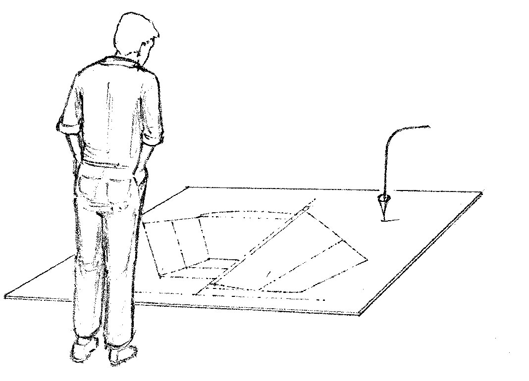
Strike a baseline on your scrive board, about 6″ from its bottom edge, and then construct a CL perpendicular to it from the baseline’s midpoint. Using pick-up sticks, transfer each station’s sheer and chine (bottom) locations to the body plan, and connect the points at each station with straight lines, remembering that the lines that represent the boat’s bottom are horizontal and square with the CL. On this boat, lines are drawn to the inside of the planking, so in making the molds there is no need to deduct plank thickness from our sections.
The basic lofting and fairing are now done, and it is time to make the building molds for each station. Transferring the lines to the mold stock is quick and easy.
Now that you understand the basics, you may want to learn more advanced techniques such as learning how to loft a round-bottomed boat. Before long, you’ll be developing curved, raked transoms with the best of ’em — and your building options will be many.
Karen Wales is the associate editor for WoodenBoat.
Further Reading
Building Small Boats, by Greg Rössel
Lofting, by Allan Vaitses
Boatbuilding Manual, by Robert M. Steward
Getting Started: Volume 15, “Reading Boat Plans,” by Mike O’Brien, WB No. 207
Plans for the Asa Thomson skiff are available at The WoodenBoat Store, WoodenboatStore.com.

