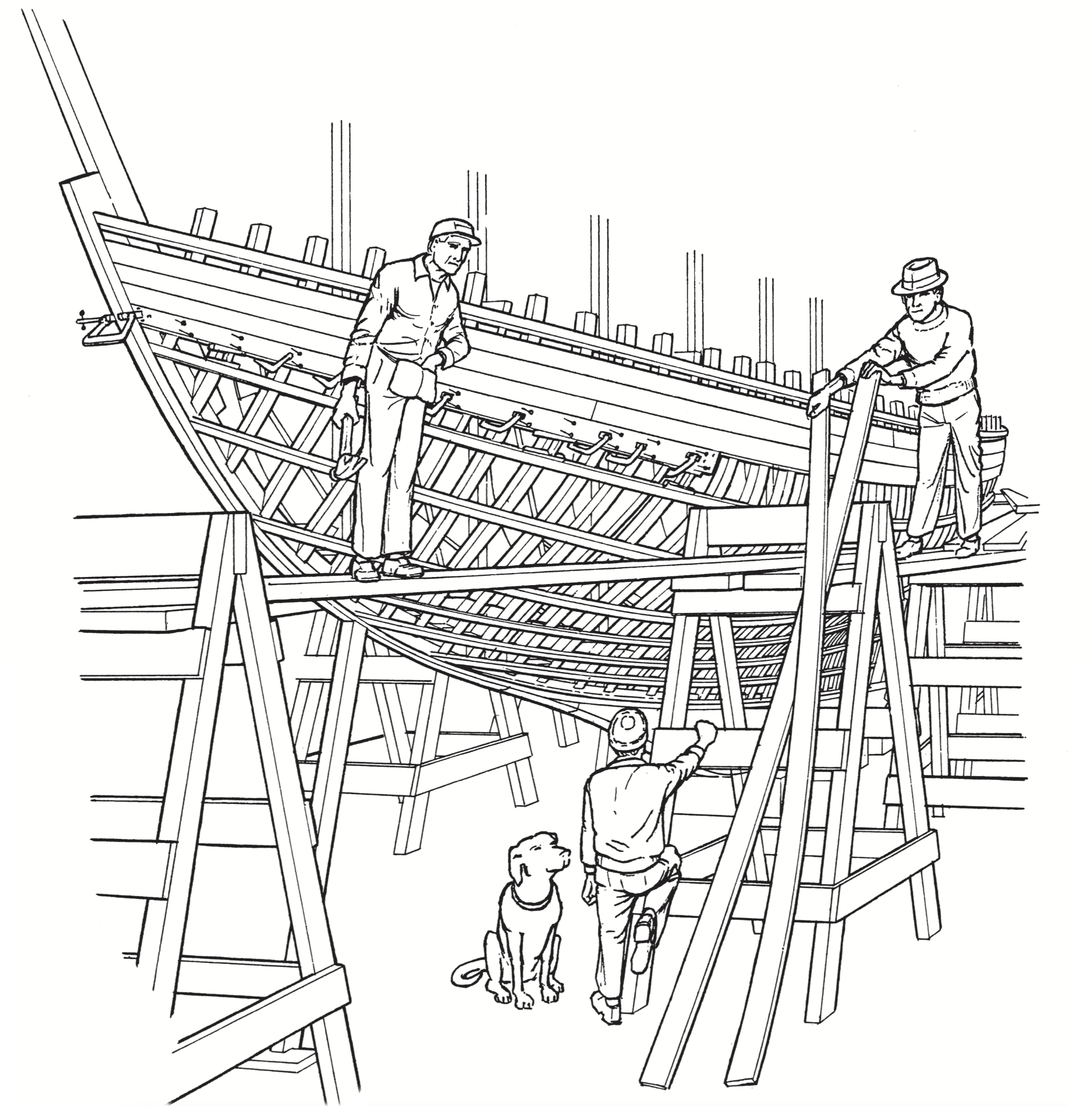
The glossary will say something like this: “Floor timber-an athwartships member, usually of wood, used to tie the heels of the frames to the keel.” This definition comes close to being the ultimate in oversimplification. The floor timbers provide a base for the engine bed, intermediate shaft bearings, and a mast step. They tie the two halves of the boat together down where it really counts. They take in hand the enormous wringing strains of the ballast keel, and transfer these loads smoothly and subtly to the main fabric of the hull. They connect a flexible keel to the longitudinal rigidity of the topsides. They even provide support for a platform to walk on. Unfortunately, they are not always provided in sufficient numbers, styles, and sizes to do this work in a satisfactory manner.
Various types of floors
I can think of seven different forms in which this member can appear, each one with certain virtues of its own (Figure 8-1 ). There’s the simple plank-on-edge, suggested by the above definition, which can go before, abaft of, on top of, or between the frames. In its best form this simple floor is shaped from a “grown crook,” with long arms up the inside of the planking. You are most likely to find it in a primitive boatyard where the builders live close to the forest and time is not of the essence-and you can well envy them their pile of sweeps and knees, because we can’t improve on them a bit with all our refined techniques. There’s the metal floor-forged from wrought iron or steel, or cast in bronze, or welded in web form from bar and angle stock.
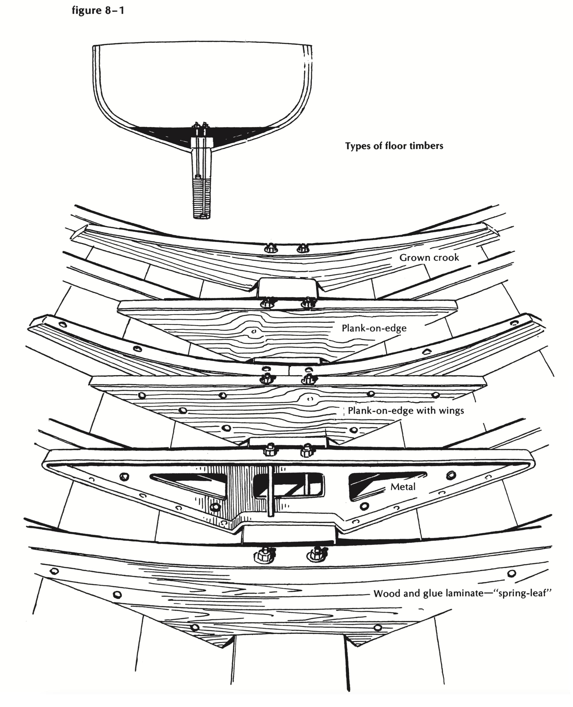
Figure 8-1
This usually is used up forward, where an honest plank floor would stand too high and spoil the headroom. It’s a pretty thing, and very expensive; but it sometimes fails to do its job. I’ll have more to say about this later. (Once upon a time, there was a special rating rule in the Great Lakes which for some reason penalized inside ballast, as distinct from structural members. One boat appeared with a 600-pound bronze fairing piece on the lower end of the rudder stock; another used, in the refrigeration system, bronze tubing with a 2-inch-thick wall. Needless to say, the designers of these boats went wild with metal floors. In my innocence I contracted for and built one of them, and the old scars act up when I think of it. I have suffered since from the failings of three others that came here in mid-career and drooped their chins, as it were, on my doorstep, asking to be made whole again-and I learned a lot about floors from them.)
And there’s the spring-leaf floor (Figure 8-2), built up of glued laminations, saturated and sealed with super-epoxy, light, stiff, strong, and guaranteed not to delaminate as long as the moisture content stays the same. It is also frightfully expensive, but worth every nickel if you are building a three-ply featherweight to the quarter-ton rule. Such a boat is outside my experience and beyond my desire. However, if my boat won’t get there the same day, it’ll make it the same summer, fortified by massive, heavy, perhaps crude floors that’ll never let a garboard swing open.
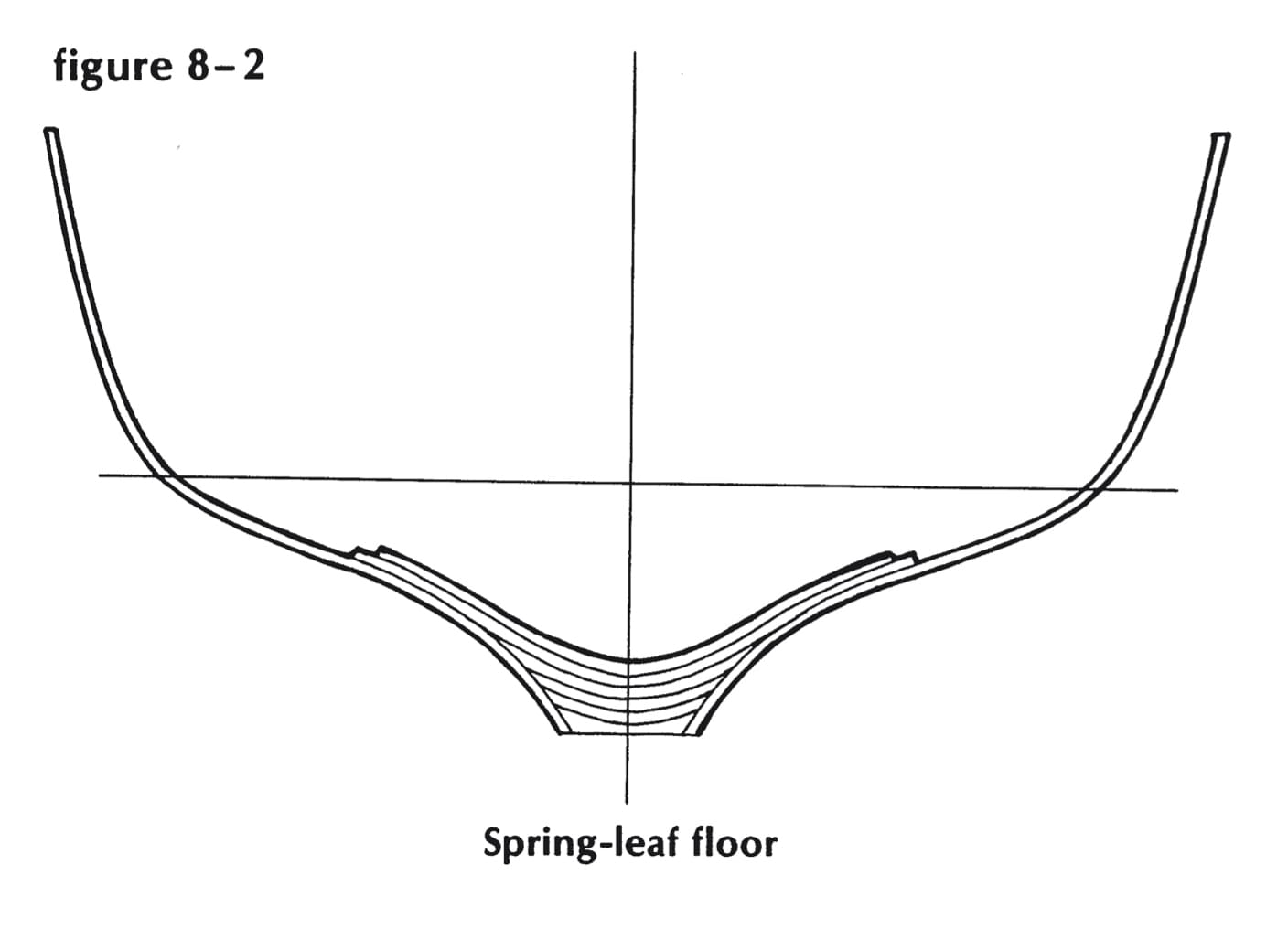
Figure 8-2
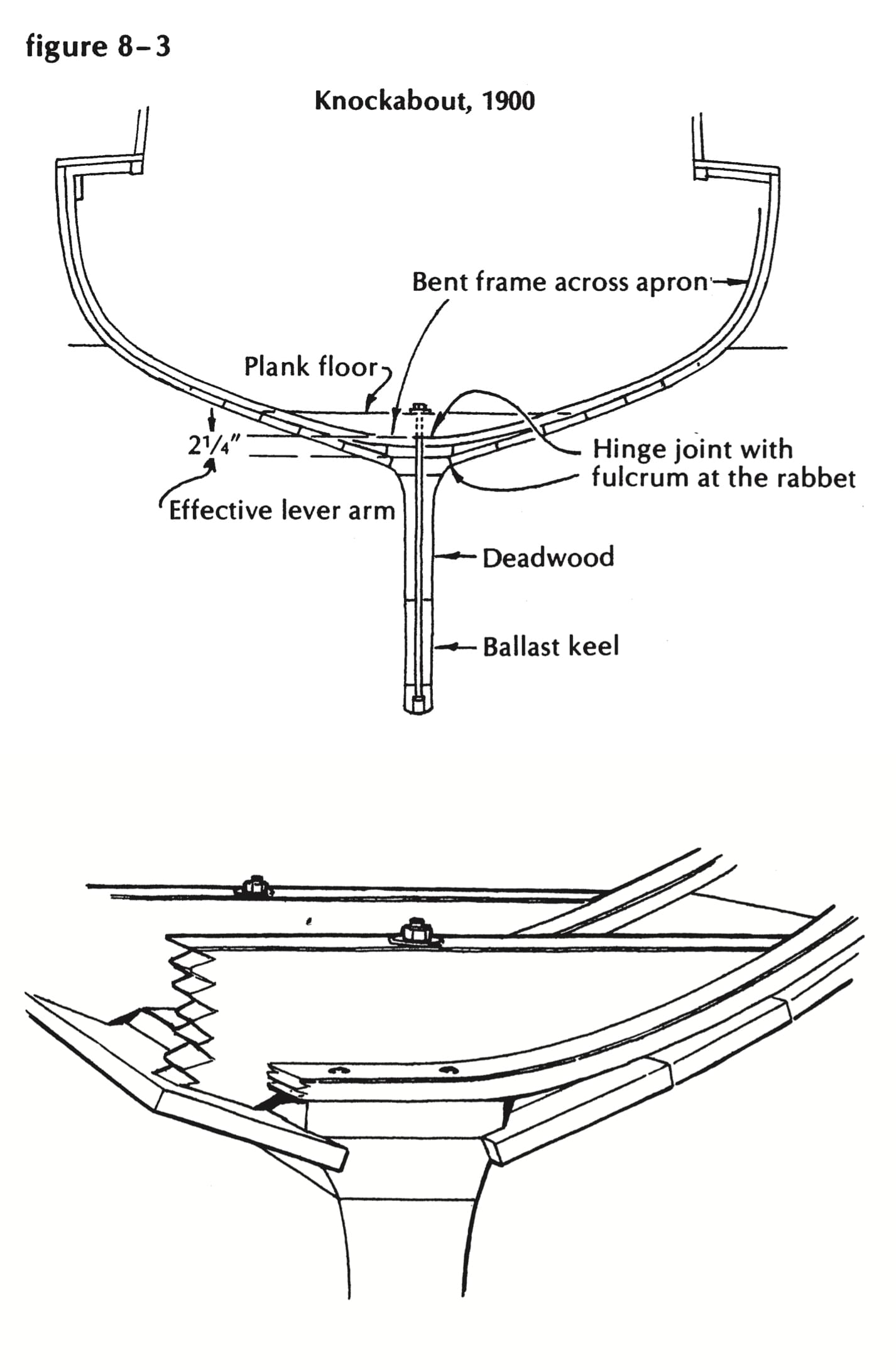
Figure 8-3
Let’s contemplate some of the stresses that occur in a sailboat with outside ballast. We’ll stand the boat on edge and drop her off the top of a 6-foot sea that hits beam-on. Look at “Knockabout, 1900” (Figure 8-3). This boat probably leaked very little in its youth, even when driven hard. But despite splendid workmanship and tender loving care, the fastenings and joints would eventually work loose and allow for cruel leaking. Caulking would aggravate the trouble; the only cure would be more and bigger floors, with bigger bolts through them. And don’t tell me you can fiberglass the bottom and make her as good as new. You’ve got to stop that wiggle first.
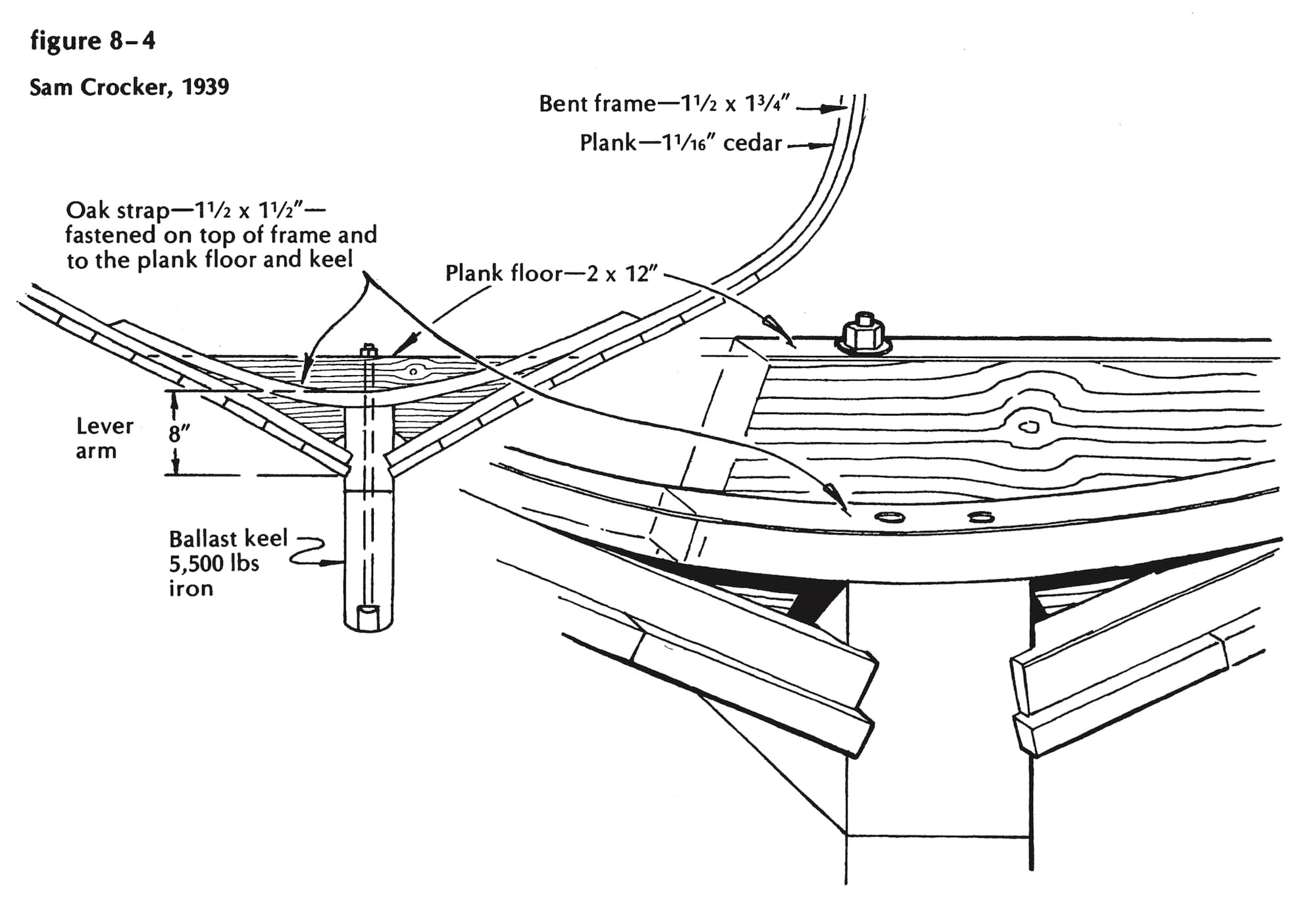
Figure 8-4
Now look at “Sam Crocker, 1939” (Figure 8-4). This is much better. (We were building Fomalhaut then, and trying to learn all we could from Sam Crocker; there was a lot he taught us-one lesson having to do with that particular keel-floor-ballast configuration. It seems that even he had had secret doubts as to its ultimate indestructibility, so when he started across country, after the 1938 hurricane, on the trail of one of his 30-footers, he counted the successive trenches her keel had gouged. His heart sank lower and lower as he approached the 50 mark-and there the little so-and-so sat, leaning against an oak tree. “Christmas!” said Sam. “She hadn’t even squeezed the putty out of the garboard seam!” He told of another case in which they hadn’t, for some reason, boxed the frames into the foundation; that boat always leaked a little when they drove her hard, and they couldn’t cure it.)
If we accept the garboard (in the rabbet) as the fulcrum in this diagram of forces, then the lever arm to the top of the keel is at least four times as long in the second instance as in the first. Add the greater depth of floor, the thicker bolt, the boxed-in heel, and the bent timber across the keel and atop the frames, and you have a very strong structure, perfectly suited to a stand-up keel.
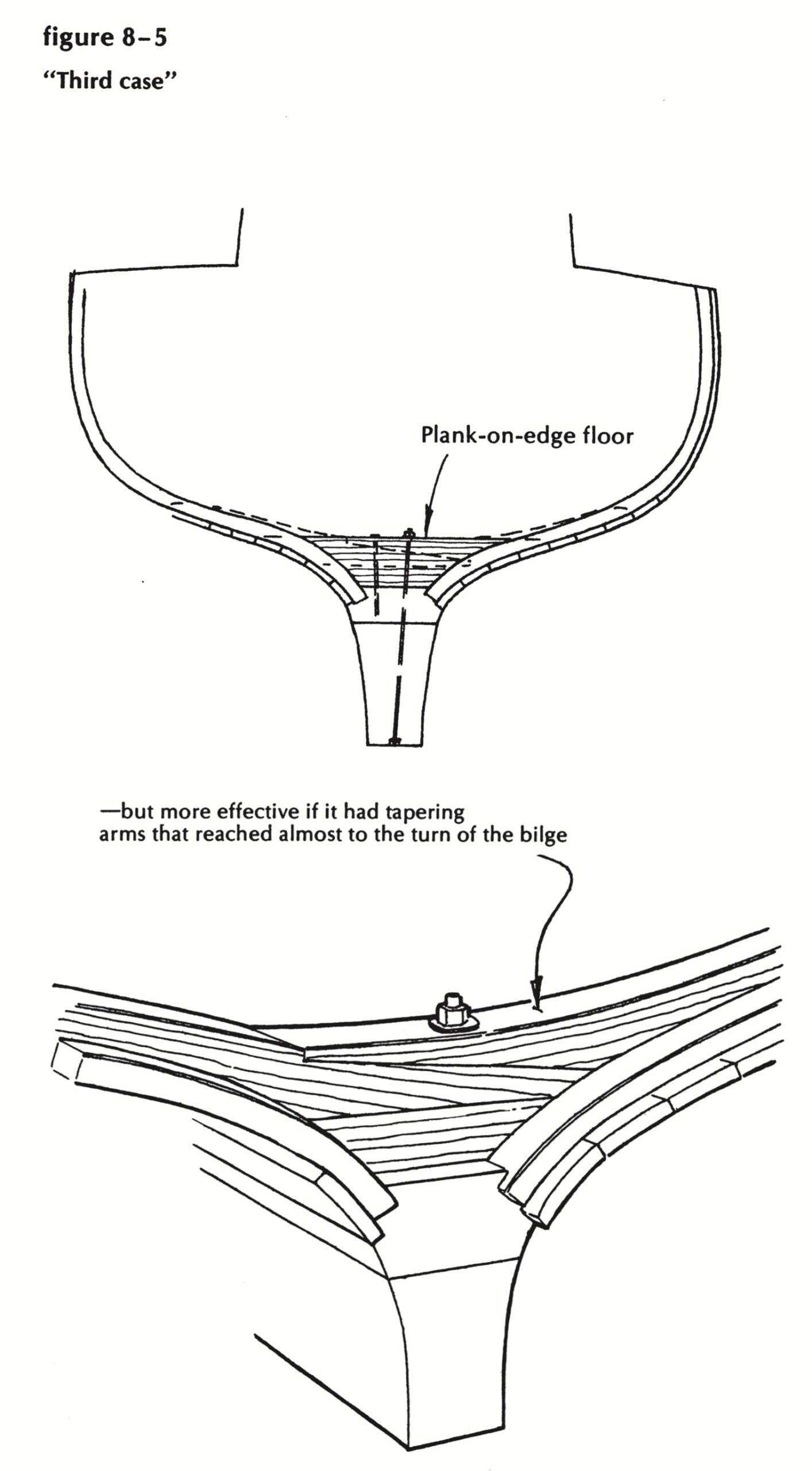
Figure 8-5
Now look at the third case, illustrated in Figure 8-5. This shows the usual molded keel, wide in the way of the outside ballast, tapering both ways to the siding of the stem and sternpost, and only as deep in profile as necessary to provide an adequate junction for frames, floors, planking, and ballast shoe. A plank-on-edge floor will do nicely here-drift-fastened to the keel, heavily fastened to the two or three planks that cross its ends. But it would be far more effective if it had tapering arms that reached almost to the turn of the bilge, strongly secured to eight or nine planks on a side and directly attached to the ballast keel, if possible. This line of thought (or yearning?) has led me to design and use, in my latest half-dozen big boats, what you might call a composite-construction floor. It’s not difficult to shape, it’s enormously strong, it allows easy access to the keel bolt, and it spreads the bolt load across the entire width of the wood keel.
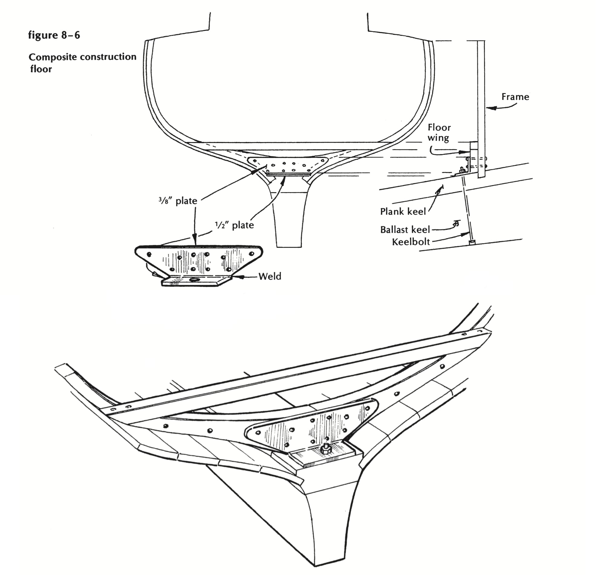
Figure 8-6
The composite construction floor
Start with a piece of½- by 4-inch steel long enough to reach almost across the top of the wood keel in the way of a ballast-keel bolt. Make a pattern for a vertical plate, or web, comfortably smaller than the width down there in the ditch. Get your friendly metalworker to cut this out of 3/s-inch plate and weld it across the forward edge of the first piece, to stand plumb, as in Figure 8-6.
Drill the bottom plate for the keelbolt; drill at least five holes on each side of the centerline in the vertical plate; drop the assembly down to the top of the wood keel, with 2 inches of threaded keel bolt coming up through the cross plate. Shim it 1/s inch clear of the top of the keel, turn a nut on finger-tight, and proceed to fit the wings-sawn to shape out of the toughest white oak or locust that ever grew, scribed to fit snugly against the inside of the planking, and extending out and up at least to the underside of the cabin sole. Clamp to the plate and drill the wood to match the holes in the plate. Mark where the wings lie on the planking, and punch lead holes out through to lead the screws that will go from the planking into the wings.
Take the whole business apart; apply zincrich paint to the metal; set the athwartships plate on a fine bed of canvas gasket and tar-and oakum grommet, but don’t tighten the keelbolt nut until everything else is bolted and screwed together. That last 1/8 inch (with roofing tar squeezing out around the edges) will take up all the slack. The final move is to fit and fasten a fine timber across from tip to tip, at the height of the underside of the cabin sole. You can spike and screw-fasten the ends as shown, or you can fit a metal plate on each side and through-rivet to tie things together.
I think you’ll be satisfied with one of these floors in every other bay (say, 24 inches apart) and view with pleasure the chance you have to install worthwhile fuel and/ or water tanks below the cabin sole-but be sure you can get them out without disturbing the joinerwork. You might want to check a keelbolt after 20 years, or you might have to clear the limbers, or convince a surveyor that there’s still a sound boat down in that hole. Before we finish comparing timbering systems, look at Figure 8-7, which shows typical big-ship double-sawn frame-with-keelson construction.
New bootstraps
I’d like now to consider some of the responsibilities of the floor timbers, how they can fail in their duties, and what can be done to get them out of a bind.
There is a subject dear to my heart best described as The Case of the Shrinking Garboard. This crops up most frequently in “planked-down,” “ditch-keel” powerboats like Old Novis, but I’ve known the phenomenon to occur in an ancient Crowninshield schooner and a classic fantail-stern launch. The opening move is always the same. “Have you got any real good oakum?” asks the owner. “My garboards have shrunk something awful. ‘Course, they’re original-been on there 15 years-can’t expect them to last forever-anyone knows you can’t do a real caulking job with cotton …. ”
So you tell him you think she needs new bootstraps more than she needs further prying apart. (Garboards don’t shrink, all evidence to the contrary notwithstanding. Keels sag under the weight of engines; and if the frame-butts let go their grip of the foundation, there’s bound to be a gap above the rabbet. You can’t blame the trouble on floor timbers, because they were not provided in any great quantity when the boat was built.) If you are as foolhardy as I have been known to be, you will tell him to bring her up, and you’ll put her on the railway; and if he’ll tear up four feet of cockpit floor down the middle, you’ll fix her.
So you haul her out, with water in her up to the flywheel, and not a drop runs out of the old basket. But put a timber and a jack under each bilge, just aft of the engine, and take half her weight off the car-and the ocean drops right out of her lovely garboard seams. While she’s up thus, rake out the lovely mess of cotton, oakum, and roof tar from the garboard seams, and let her down again. Chances are those garboards have miraculously expanded (or something has happened, anyway) so now the open seam looks almost respectable. All you need worry about is keeping it that way when she’s supported by water instead of by railway.
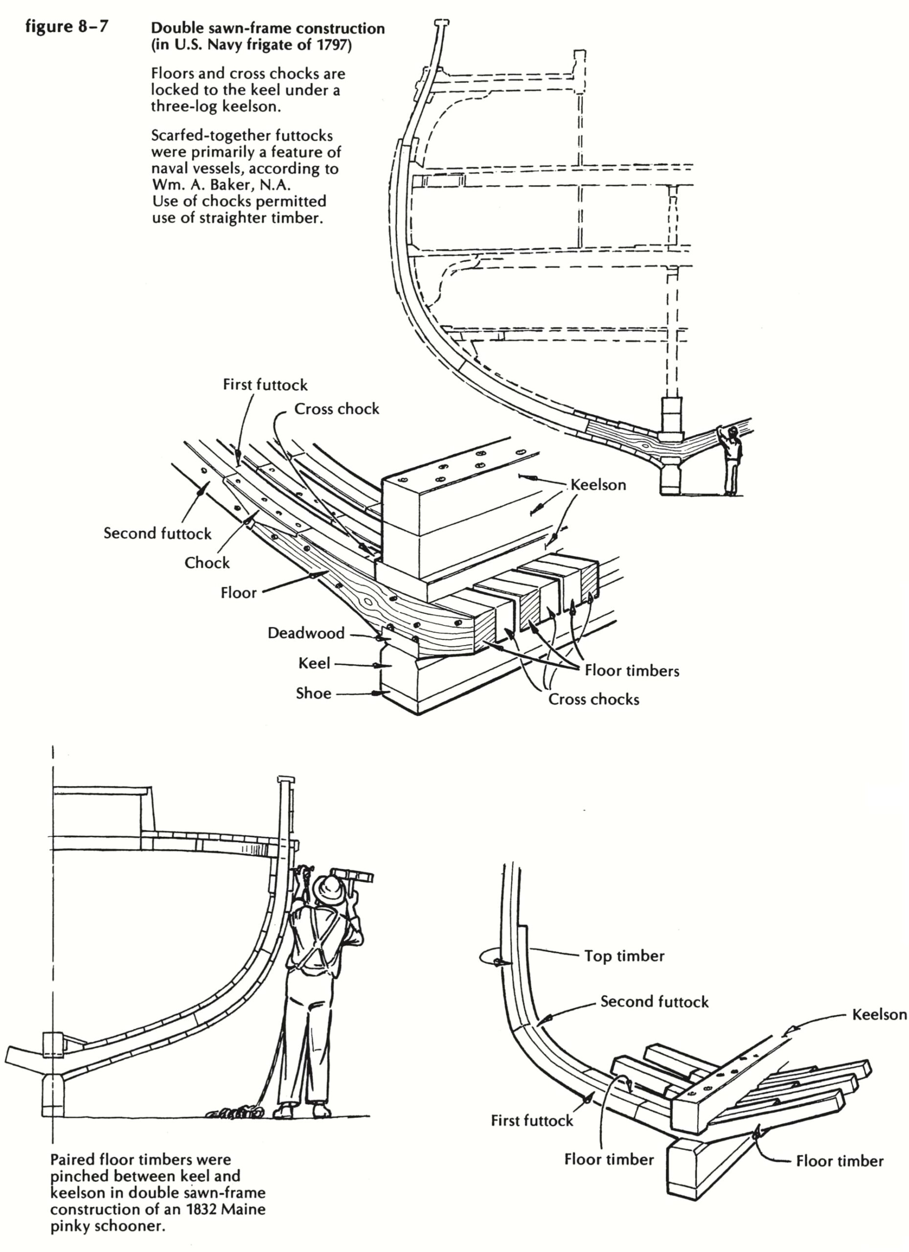
Figure 8-7
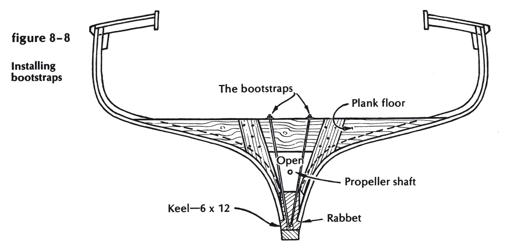
Figure 8-8
Here’s where the bootstraps are applied. First, look at Figure 8-8. That timber sitting on edge across the ditch is brand-new to this old boat, and is one of three, judiciously spaced between the sternpost and the forward end of the cockpit. I call it a floor timber for lack of a better name. Bore a hole down through it, far enough off the centerline to clear the propeller shaft. Continue the hole down through the keel. Cut and thread bolts to reach from countersunk heads on the bottom of the keel to the top of this cross piece. Do the other two likewise; fasten earnestly from the planking into these pseudo-floors; fit vertical cleats, wedges, and fillers down each side of the ditch, bolted to the crosspiece at the top, fastened to the planking below. Tighten the nuts on the bootstraps ’til she squeaks in pain. Caulk that fine small garboard seam and shove her back in. You shouldn’t have missed more than one tide.
(We did Brooksy’s gramp’s boat this way one morning. She was strip-planked, and not too old, and sat on the railway tighter’n a you know-what in flytime until we jacked her a little-whereupon 1,000 miles of hairline seam appeared in view, oozing water every damned inch. We put the bootstraps to her, as above, and shoved her back in to adjust herself. Saw Cramp a week or two later looking kind of morose, and felt obliged to inquire how she was doing. “She stinks!” he said. “Used to be you pumped enough water through her to keep her sweet, but not any more. That gurry just sets in the bilge and rots.” Ah, well … some days you can’t do anything right.)
With all these pictures of flat-floored powerboats around, this is a good time to consider another special responsibility of the floor timbers-or perhaps what happens, in this type of boat, when they’re too small and too few.
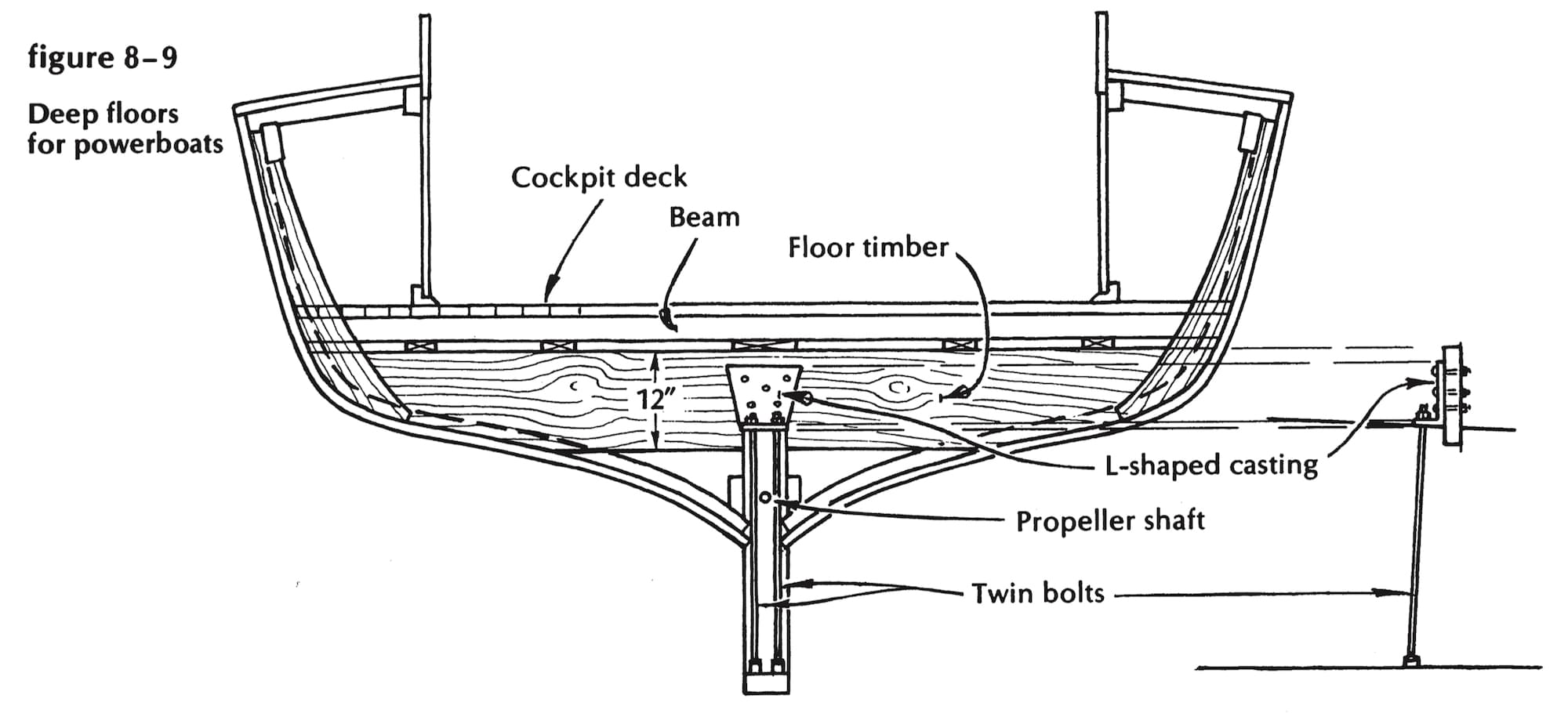
Figure 8-9
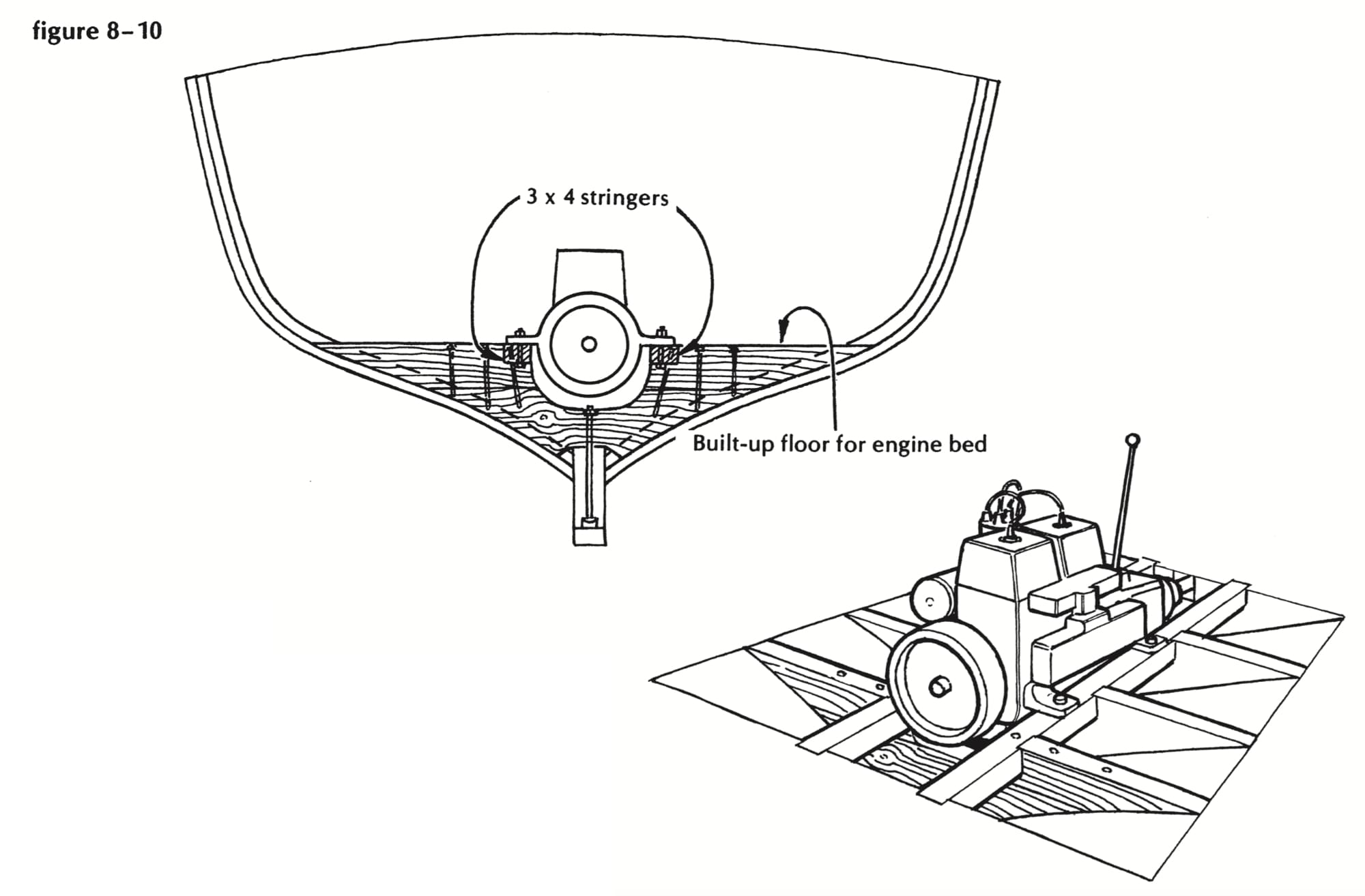
Figure 8-10
Fitting deep floors
Let’s agree that the topsides of the boat (the side planking from just below the waterline to the sheer, in my book, and never mind what the Navy calls it) provide most of the longitudinal stiffness of the hull. The keel contributes very little to this (unless, of course, we are considering a heavily built dragger, with considerable deadrise even in the after sections), and the great need is to transfer this topside strength to the rest of the fabric, including the keel. This is one of the main functions of the floor timbers. Go to any graveyard of old lobster boats, and you’ll see what I mean. If they’ve sat long without careful shoring under the bilges and transom, they’ll likely show a dimple at the top of the sternpost and a kink in the keel where it rests in the forward-most crossbeam of the cradle. The bilges may sag a bit, like the jowls of middle age; and in a planked-down boat there will be a definite coming-together of the sides above the shaft alley.
You may argue at this point that the boat was designed to float in water, and not sit up there in the weeds. True enough; flexibility is a great virtue if you don’t have too much of it, and they all have to leak a little or they wouldn’t be boats-but what if you hit the sand a few times while running an inlet, or get caught in the surf along the beach? You’ll feel better if you know the garboards aren’t likely to pop out of the rabbet on the third bounce, nor the stern post to come up through the deck, nor the propeller shaft to go so much out of line that the engine is lost.
You can take arms against this sea of troubles thus: Fit long floors clear across the flat, as in Figure 8-9. Make them as deep as you can; bolt a vertical member at each end, pinned to the sheer clamp, where possible; fasten them solidly to the backbone with drifts and Lshaped castings locked to the twin bolts in the deadwood. The athwartships strength of these deep floors will hold the topsides and centerline structure in their proper relationship. The floors provide a perfect base to support the timbers of the cockpit floor frame. And they add 207 pounds to the weight of the boat, and 15 years to its useful life, and reduce its speed by 9/Jo knot. You may question the accuracy of these figures, but it won’t do any good to tell me about it.
While we’re still aboard this powerboat, let’s consider the engine bed and the floors that support it. Remember that the mighty thrust of the propeller must be transmitted from engine to bed to floors to hull, and that the whole assembly will be subject to violent lurches and possible sudden stops. You’re not concerned merely with a weight of 500 to 1,500 pounds sitting serenely upright. Someday it will tilt 45 degrees and drop 6 feet in the trough between seas. The usual plank-on-edge engine bed won’t stand such treatment without strong lateral support. As shown in Figure 8-10, thi, support can be provided by adding to the height of the floors, outboard of the engine mounts. Or you can fit one-piece floors, scooped out to take the crankcase, and land the engine mounts on flat stringers notched into the floors. This system allows you to use throughbolts in the engine mounts, because the lower ends of the bolts are in the clear below the stringers.
If you tie all these members to each other, and to the keel and frames and planking, and anything else you can think of, then you can feel fairly certain that the bed won’t wrack or loosen. And if you are installing two engines side by side, make these floors high and plenty where they cross the keel; lock the engine bearing stringers into partial bulkheads before and abaft the engines, and don’t allow the weight to bear on the frames and the planking. (I’ve seen three-year-olds with double hernias.)
Adding timbers with “wings”
Let’s now take a good look at the front end of a long-snouted sailboat. She’s got a fine pedigree, metal floors up forward, and a frantic owner. He has read all about inadequate mast steps and outside strapping in the Herreshoff manner, but he’s not quite sure what to do, because she leaks-not too badly at rest if the rigging is slack, but fearfully indeed when she’s under sail. She’s a $50,000 deathtrap that’s worth just what the gear will bring on the second-hand market-unless, of course, we can think of a cure, preferably quick and inexpensive.
Let’s try to analyze the trouble. Obviously, the garboard seam ( or much less likely, the joint between the keel and stem) opens when the mast pushes down and the shrouds pull up. It’s customary to blame this phenomenon on a mast step that’s too short. No one would dare blame it on a weakness of those magnificent cast-bronze floors, or the builder’s refusal to box the frames into the foundation. “Completely useless, and just another rot-pocket,” he’ll tell you. Maybe the mast step is a bit on the limber side; but if it were a cast-iron bar twice as long, it wouldn’t change things much. The shrouds are still going to pull the frames and planking away from the keel unless there’s a very strong, nonstretching tie to hold them there. (And it takes only 1/16 inch of slackness in a 3- to 4-foot length of seam to cause a leak that’ll scare you to death.)
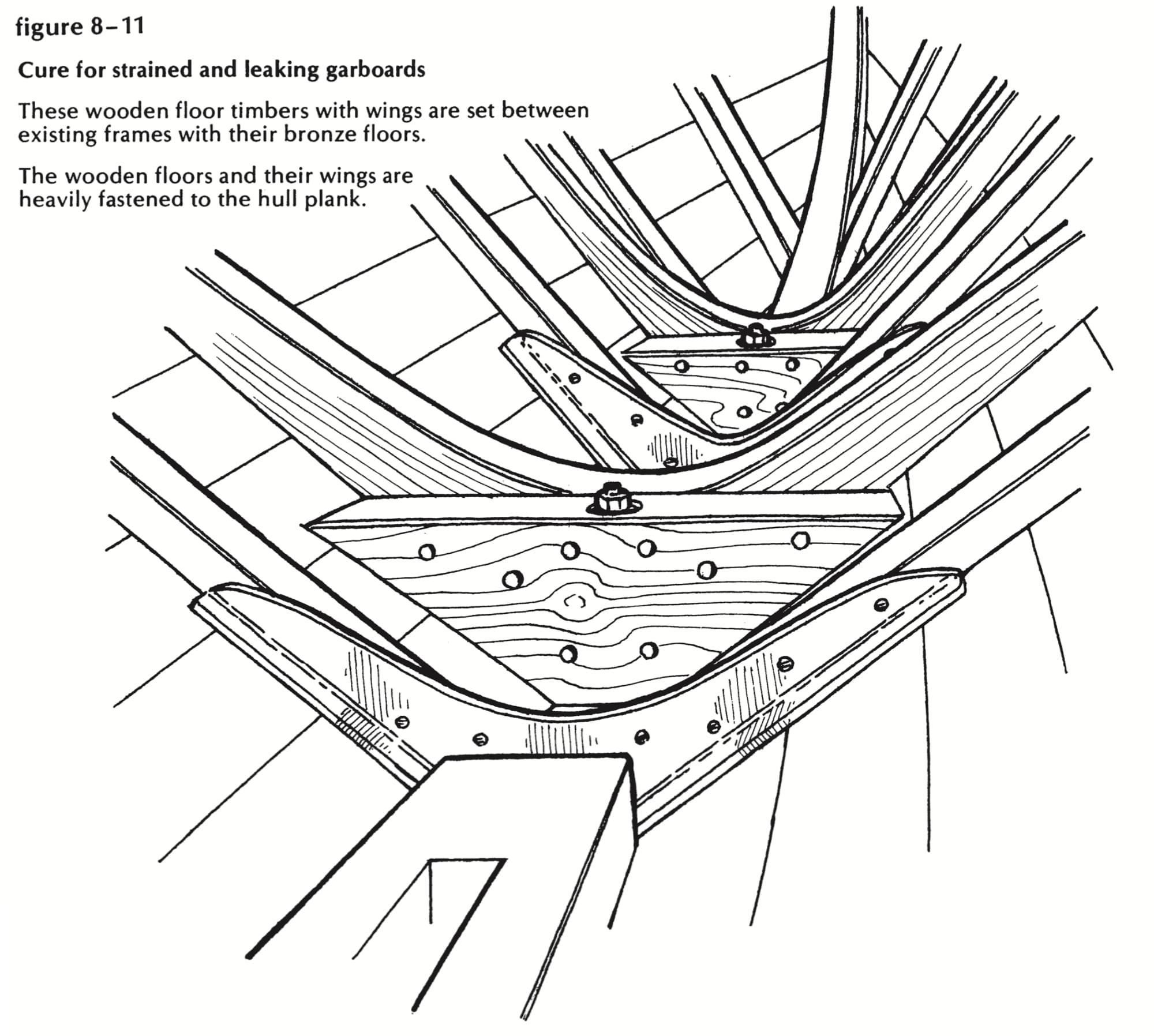
Figure 8-11
Believe it or not, the cure for this dreadful state of affairs is relatively simple. The most difficult part of the project is to convince the owner that you have to rip out all that lovely ceiling and joiner work, and leave him with 6 inches less headroom up front. Turn a deaf ear to his wails and fit some real floor timbers between frames, bolted strongly through the keel or stem as may be, fitted with wings-up the inside of the planking as far as you dare (see Figure 8-11). Fasten from the planks into the floors as if your reputation depended upon it, as indeed it may. Recaulk, hard, the garboard seam and two or three plank seams above it. Say a prayer, shove her in, and try her out. You may have gained a satisfied customer and a friend if you managed to replace most of the joinerwork intact and didn’t charge him for it.
Tangs and tie-rods
There’s yet another way to hold these parts together. It’s somewhat akin to the bootstrap technique described ‘way back there for the salvation of old powerboats, and has the great virtue of taking up practically no room at all. It’s all done with simple tangs and tie-rods. Figure 8-12 makes it perfectly obvious: Fasten the tang to a frame or rivet it to the inside of the planking; drill all the way through the stem, as nearly as possible in line with the tang; counterbore for the nut and rivet the tie-rod up and through the tang end; turn on a nut, and tighten down. The longer the tangs, the better. The more of them you apply, the better. The bronze floors can stay right there to impress surveyors, and the garboards will hold the new caulking.
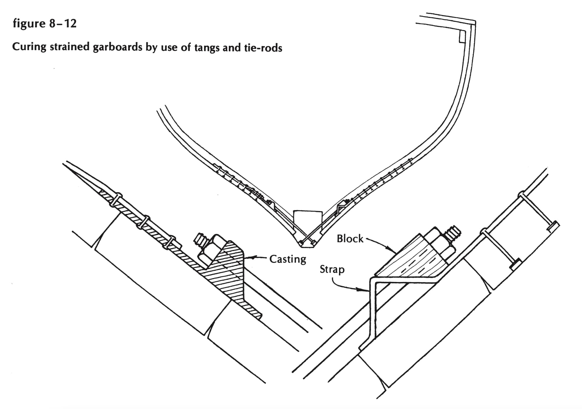
Figure 8-12
Having read this far, you may have the feeling that old boatbuilders spend most of their declining years repairing their own and others’ mistakes. This is not the whole truth. We go on making more mistakes, but we don’t usually make the same ones all over again. Profit by our examples and warnings, and try to do better. And that’s about all I have to say, right now, about floor timbers.