
Greg O’NeilChurch Mouse.
In the first installment of this series on building the Church Mouse Skiff (see WB No. 310), we made the construction jig, set up the stem and transom, planked the hull, and removed the boat from the jig. In this, the second and final installment, we complete the hull and build the rig.—Eds.
Scarlett Stevens/Arlington Career Center1. Marking and cutting the sheerline.
Marking and Cutting the Sheerline
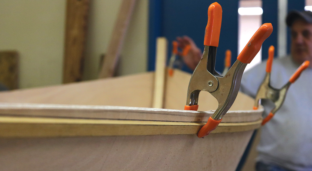
1. The side panels were purposely left a little oversized. Now is the time to trim the sheer to the marks made on the inside of the planking in Part 1 (Step 2). To do this, drill small holes (⅛″ or so) from the inside of the planking through the sides at these points. This transfers the sheer marks to the outside of the boat. Clamp a batten through those points, and through the sheer marks at the bow and stern. Check that the curves are fair on each side of the boat, and that they land at the same stem and transom heights.
When you are happy with the marked sheer curves, cut them with the saw of your choice (we used a Japanese pull saw) as close to the line as you dare, and plane down to it.
Scarlett Stevens/Arlington Career Center2. The seat cleats.
Seat Cleats
2–3. The seat cleats are made from ¾″ × 1½″ stock, rough-cut to 8″ long and then trimmed to length according to their locations. Their tops are beveled to meet the seat; you can lift that bevel from the plans, using your bevel gauge, or determine it on the boat itself. For each cleat, the face that meets the side must be scribed and shaped slightly to fit the slight curvature of the side panel.
Joe Youcha3. The seat cleats.
The cleats’ fore-and-aft locations are measured from the mold positions, which were marked before the hull was removed from the jig; their heights are measured down from the sheerline. Each pair of dimensions, for each of the cleats, is indicated on the plans. Draw the outline of each cleat on the side plank, and then drill two evenly spaced small holes (⅛″ or so) from the inside that will then locate the countersunk pilot holes to be drilled next, from the outside, through the plank and into the cleat. Then apply adhesive to the mating face of the cleat and fasten it in place.
Joe Youcha, Scarlett Stevens/Arlington Career Center (far right)4, 5, 6. Pattern, cut, and install the thwarts.
Pattern, Cut, and Install the Thwarts
4–6. The ideal thwart stock is clear ¾″ × 9″ spruce, pine, cedar, or fir. To pattern the thwarts, first make shims the thickness of your thwart stock—these will be used to elevate the pattern stock to match the top surface of the thwart so that its longest dimension can be established first.
The ends of the thwarts are shaped to match the curves of the boat’s sides; pattern the thwarts using the same stick-and-hot-melt-glue method used to pattern the cross spalls as shown in Part 1 (Step 26). Mark on the pattern where the forward and after edges of the thwarts will intersect the sides of the boat.
Lay the patterns on the stock and draw the outlines of the thwarts. Set your bandsaw to the correct bevel and make the end cuts.
The underside of each thwart is beveled along each edge; this elegant detail reduces the thwarts’ apparent thickness.
Three 1½″ No. 8 screws set flush to the top on each end will fasten the thwarts in place to the cleats. But don’t install them permanently yet; they will be in the way of the framing operation. And don’t use adhesive or bungs when you do; the thwarts are meant to be easily removed for painting.
Scarlett Stevens/Arlington Career Center7. Make the quarter knees.
Make the Quarter Knees
7–12. Well-placed and -proportioned quarter knees enhance the boat’s structure and appearance. Although these knees require compound angles on two surfaces—and one of those surfaces is slightly curved—the process of shaping them is straightforward. Begin by drawing a straight line from sheer to sheer across the inside face of the transom.
Scarlett Stevens/Arlington Career Center8. Make the quarter knees.
Next, use a compass set to 6″ to swing an arc on the the transom and side at the sheer. Make a mark 1″ up along this arc from the line you just drew across the transom, and draw a line on the inside face of the transom from this point back to the point from which the 6″ arc originated. This line indicates the top surface of a quarter knee; repeat the process on the other side. On the sheerline on each side panel, make a mark 8″ forward of the transom face to indicate the forward reach of each quarter knee.
Scarlett Stevens/Arlington Career Center9. Make the quarter knees.
Now it’s time to make a pattern of the knee from stiff cardboard, thin plywood, or Masonite. Place a straight edge of the pattern stock against the inside face of the transom at the correct angle. Trace the inside of the side onto the pattern stock, and transfer the 8″ mark onto the pattern. Then transfer the 6″ mark from the transom onto the pattern. Cut out the resulting pattern, leaving enough pattern stock for the inside curved face of the knee—but don’t mark this decorative shape until after the outside edges are fit, because a little trimming will still be required. With the pattern back in place, use a bevel gauge to pick up the angles of the edges that bear against the side and transom; mark these angles on the pattern.
Joe Youcha10. Make the quarter knees.
Scarlett Stevens/Arlington Career Center11. Make the Quarter Knees.
For strength, the grain of the wood should follow the shapes of the quarter knees as best as it can. Crooks, with their curved grain, are ideal, but if you’re using straight-grained wood, orient the pieces as shown in the drawing; this gives you a minimum of short grain. Set your bandsaw to the correct angle for each edge and make your cuts.
Scarlett Stevens/Arlington Career Center12. Make the Quarter Knees.
Once you’ve got the outside edges fine-tuned to fit against the transom and side, lay out the curve of the inner shape of the knee and cut it with the bandsaw set at 90 degrees. Round-over and finish this edge with a rasp, file, and sandpaper.
Scarlett Stevens/Arlington Career Center13. Install the Quarter Knees.
Install the Quarter Knees
13. Draw the outlines of the quarter knees on the inside face of the transom. Using a small pilot bit, drill two evenly spaced holes from the inside. In order for your screws to not come out the top of the quarter knee, these holes must follow the plane of the quarter knee’s surface instead of being perpendicular to the transom face. Next, with the quarter knee in place, lay out and drill three evenly spaced countersunk holes for the screws fastening it to the side. Again drill the holes parallel to the surface of the quarter knee. Drill the countersunk holes for the two transom screws at this time, too. Bed the quarter knee mating surfaces in polyurethane sealant and drive the screws.
Scarlett Stevens/Arlington Career Center14. Mark, Make, and Install the Breasthook.
Mark, Make, and Install the Breasthook
14–18. The breasthook holds the bow of the boat together. You can take its shape from the pattern on the plans, or pattern it yourself from the actual boat. The process of making it is similar to that of the quarter knees. Additionally, there’s a little jig-making.
Scarlett Stevens/Arlington Career Center15. Mark, Make, and Install the Breasthook.
To pattern the breasthook, make marks on the sheer edge of both side panels 8″ aft of the stem. Carry these marks onto the inside faces of the sides; they indicate the after ends of the breasthook. Cover the area with your pattern stock with a straight edge of the stock up against the inside edge of the stem, and trace the inside edges of the sides. Onto the underside of the pattern, mark the after ends of the breasthook. Cut out the pattern.
Measure the angles between the breasthook and sides, and breasthook and after face of the stem, and mark them on your pattern, just as you did for the quarter knees.
As with the quarter knees, the grain of the breasthook must follow its shape. A grown piece—the crotch of two branches—may be hard to find but is ideal because the grain will wrap around the piece. If you’re working with straight-grained wood, you’ll need to glue up an assembly of pieces to maximize their grain direction. For this, you’ll need a jig. For more than 30 years, I’ve been using a jig Tom Hill wrote about in his book Ultralight Boat Building. As indicated in the drawing, a plywood base, two cleats, two wedges, and two C-clamps are all you need for this jig.
Scarlett Stevens/Arlington Career Center16. Mark, Make, and Install the Breasthook.
There’s a lot going on in this illustration; study it until it becomes clear. The breasthook blank is made from three pieces: a rectangular straight-grained centerpiece, and two trapezoidal wing pieces with their grain running parallel to their long edges. In the photograph below, we made the center piece extra wide with three pieces for an artistic detail. It’s fine to use a narrower (¾“) single piece.
Scarlett Stevens/Arlington Career Center17. Mark, Make, and Install the Breasthook.
Test-fit your pieces. Once you’re comfortable with the edges fitting well against one another, test your jig. Set the breasthook pieces and wedges snugly into the jig. Clamp the “wing pieces” in place, snug but not too tight. Drive wedges. Tighten the clamps. If it all works well, take it apart, spread glue (Titebond III or epoxy) on the mating surfaces, and repeat the assembly process. Use a piece of plastic between the blank and the jig to keep the breasthook from sticking to the jig. Driving the wedges should yield good squeeze-out; clean it up as best you can.
Scarlett Stevens/Arlington Career Center18. Mark, Make, and Install the Breasthook.
When the glue is dry, remove the blank from the jig and clean up any excess. A plane, paint scraper, or a belt sander will work well for this task. Using the bevels you marked on the pattern, set the bandsaw and make the cuts as you did for the quarter knees. This time you have three angled cuts: the two sides, and the stem. I make the saw cuts a heavy ¹⁄₁₆″ outside the line to allow the breasthook to stand ⅛″ to ¼″ proud of the sheerline; the extra material allows me to plane, rasp, or sand a crown into the top of the breasthook, which sheds water and looks better than a flat surface.
If you’ve patterned and cut well, your cut surfaces should need just a little filing or sanding to remove the saw marks and your piece should fit. Once you’re happy with the fit, mark and cut the after portion of the breasthook according to the plans.
Scarlett Stevens/Arlington Career Center (both)19, 20. Make and Install the Frames.
Make and Install the Frames
19–20. There are three pairs of frames. The forward two pairs are made wider in the area where they intersect the thwarts to allow for adequate fastening of the frames to the thwart edges. Unlike the aftermost pair of frames, these frames fit into the boat athwartships; they are not set at 90 degrees to the sides, so their outer edges must be beveled to fit the sides. The bevels and frame shapes are indicated on the plans. The forward frames fit against the after edge of the forward thwart. The ’midship frames fit against the forward edge of the center thwart. The after pair of frames are ¾″ by 1½″; they fit 17″ aft of the after edge of the center thwart.
For the forward frames, cut the bevels on the full 3″-wide stock first, then cut the frames to the pattern’s shape. For all of the frames, angle their bottom ends so that they fit onto the tops of the chine logs (this angle is indicated on the frame patterns). Once the frames are made and located, trace their locations onto the inside of the planking. For each frame, mark the centerline within this outline. Drill three evenly spaced pilot holes, with no countersink, from the inside along this centerline. Clamp the frame in place and drill countersunk holes from the outside for No. 8, ¾″ screws. Disassemble; blow out any dust; apply polyurethane to the frame edge and bottom. Install the frame.
Joe Youcha21. Final Fitting and Installation of Thwarts.
Final Fitting and Installation of Thwarts
21. Now fit the edges of the thwarts to the frames, which may take some minor chisel work. For each forward and ’midship frame, drill pilot holes for two No. 8, 1½″ screws to go through the frame into the edge of the seat. Fasten frames to the thwarts.
Scarlett Stevens/Arlington Career Center22. Make and Fasten the Rails.
Make and Fasten the Rails
22. The rails are 1″ wide by ⅝″ thick. Taper them to ¾″, starting 18″ from their ends, and bend them ahead of time, as you did the chine logs, to the curve shown on the plans. The rails are fastened from both the outside and the inside. From the outside, three 1¼″ screws go into the breasthook, one each into the frame heads, and two into the quarter knees. To avoid hitting existing screws, mark the locations of the screws fastening the quarter knees and breasthook to the sides. Use a combination square to draw a line ½″ down from the sheer on the inside of the side panel, and mark for three evenly spaced No. 8, ¾″ screws between the frames along this line. Bed the rails in polyurethane; clamp from the middle to the ends; drill pilot holes, and install them.
Once the thwarts, quarter knees, breasthook, frames, and rails are installed, you can safely remove the spreaders installed in Part 1 to hold the shape of the hull.
Will Sturdy/Brooklin Boat Yard23. Cut and Install the Keel and Skeg.
Cut and Install the Keel and Skeg
23. This boat has a two-part keel with a skeg and a batten. Use the pattern and dimensions from the plan to make the triangular skeg from ¾″ stock. Rip a ¾″ × ¾″ batten that’s a little longer than the bottom. With helpers, turn the boat upside down. Mark the centerline on the bottom by finding the centers of the transom, mid frame, and stem and drawing a straight line through those. Then draw lines 3⁄8″ to each side of the centerline to indicate the edges of the keel. From the outside, mark and drill pilot holes, with no countersink, through the bottom, along the centerline, about 4″ apart.
Test-fit the keel batten on top of the skeg. If the fit is good, apply polyurethane adhesive to the mating surfaces—to the skeg where it meets the bottom, and to the bottom of the keel. Clamp or hold it in place and drill countersunk pilot holes from the inside through the pilot holes you drilled from the outside. Then, fasten the keel with No. 8, ¾″ screws. (You can use a couple of 1½″ screws for the aftermost ones that go into the skeg.) This is one of the few times I don’t recommend blowing out any dust in the joint, because it’s too hard to clamp and relocate the keel. Once the assembly is fastened from the inside, from the outside drill for and drive a No. 8, 1½″ screw through the keel into the heel of the stem.
The after end of the skeg and keel assembly is fastened by a ¼″ machine screw, whose location and angle are indicated in the drawings. The screw’s head is countersunk below the surface of the skeg’s edge and plugged. Using a long 1⁄4“ drill bit, drill the hole through the skeg and the bottom of the boat. It helps to have someone sight your drill bit from the side of the boat to make sure you’re drilling at the correct angle.
Joe Youcha (top drawing), Scarlett Stevens/Arlington Career Center24, 25, 26. The Outer Stem.
The Outer Stem
24–26. If you didn’t make the outer stem when you made the inner stem, use pointer sticks hot-melt-glued to a reference board to pattern its shape, as shown in photo 25.
The outer stem, which is ⅝″ thick and ⅞″ wide, can either be steam-bent or laminated. If you laminate, as shown, use epoxy or Titebond III to glue up at least five layers. If you steam-bend, choose a straight-grained piece of wood with the grain running parallel to the wide surface. Use the pattern to make a bending mold out of 2×6 lumber; mark the points of the curve, and use finish nails and a batten to draw the curve. If steam-bending, shave ¼″ to ⅜″ off the ends of the bending jig to allow for springback. For easy clamping, cut notches on the back side of the mold to create surfaces parallel to the curve. The completed outer stem is glued to the inner stem and plank ends as shown; it is also fastened with six No. 8, 1½″ wood screws whose countersunk holes should be plugged or filled.
A nice ogee pattern, as shown on the plans, completes the stemhead. Rough-cut it with an appropriate saw; fine-tune it with a rasp and file.
Scarlett Stevens/Arlington Career Center27, 28. The Daggerboard Trunk.
The Daggerboard Trunk
27–28. Lay out the daggerboard trunk sides according to the dimensions and layout on the plans.
Cut the posts and rabbeted bedlogs according to the dimensions on the plans. Label all pieces to ensure proper orientation—mark their inside and outside. The bottom of each bedlog has a slight curve to match the curve of the boat’s bottom panel; the tops are beveled to shed water.
Attach a bedlog to each trunk side. The bedlogs are rabbeted to receive the plywood trunk sides. Apply polyurethane liberally to their mating surfaces, clamp the pieces together, and fasten with three No. 8, 1″ screws through the trunk sides and into the bedlogs.
While the trunk is still in two pieces, coat its inside faces with unthickened epoxy. When the epoxy has cured, assemble the two trunk sides together onto the end posts. Make sure that the end posts protrude ½″ below the bedlogs. Again, hold the assembly with clamps while you fasten each end with three No. 8, ¾″ screws from the outside. The posts fit through the daggerboard slot and extend through the bottom of the boat; you’ll trim them flush to the bottom later.
To clear the keel, the daggerboard trunk is positioned just off-center on the port side of the skiff; its starboard edge aligns with the edge of the keel and is fastened through the keel. The port bedlog is fastened through the bottom panel.
To cut the daggerboard slot, use a straightedge to draw a 2′ line through the centers of several screws fastening the bottom to the keel in the daggerboard area, on the inside of the bottom. This is the centerline of the bottom. Using a framing square held vertically, with the long tongue resting on the bottom and facing forward, mark the forward edge of the center thwart on the centerline of the bottom. This locates the after end of the daggerboard slot. Measure forward 10″ along the boat’s centerline to locate the forward end of the slot. Measure ⅜″ to port of the centerline to establish the starboard edge of the slot. Next, measure from this line 1″ farther to port to establish the other edge. You now have the outline of the slot. Drill holes at each end of the slot that are large enough for you to insert a jigsaw blade, cut close to the line, and finish the slot by working down to the line with a rasp or file or both. The underside of the forward edge of the center thwart must have a shallow dado cut into it to secure the trunk’s top edge, as shown in the drawing. Mark this dado by dry-fitting the trunk, carefully cut it with a chisel and mallet, and make any adjustments needed to the slot at the same time.
With the boat upside-down, draw fastening lines on the bottom and keel, half the bedlog’s width away from the slot edge. Have someone hold the trunk in position. Drill countersunk pilot holes from the outside of the boat into the bedlogs. Use No. 8, 2″ screws through the keel and No. 8, 1″ screws through the bottom. Disassemble, blow out the dust, bed with polyurethane, reassemble, and fasten.
Scarlett Stevens/Arlington Career Center29. Shape the Transom Top and Sculling Notch.
Shape the Transom Top and Sculling Notch
29. The layout of the sweet curve across the top edge of the transom starts on the inside transom face with the intersection of its centerline and a horizontal baseline connecting the points where the sheerlines on either side intersect the transom. Along the centerline, use dividers to pick up the distance between the sheerline and the top of the transom, and swing a semicircle arc of that radius. We’re going to “expand” that circle to make the curve.
Halfway between the semicircle’s center and its circumference, draw a vertical line from the baseline. Record the height of this line from the base to where it crosses the circumference of the semicircle. Call this “Height A.”
Next, divide the baseline you drew along the transom into quarters. From the one-quarter and three-quarter points, draw perpendiculars. (You already have the “two quarter” line; it’s the centerline of the transom.) Along these perpendiculars from the baseline, measure up the distance of “Height A.” Put finish nails at the one-, two-, and three-quarter points; then spring a batten along these nails, and use it to draw the curve along those points and the outer edge of the sides at the sheer. Cut slightly above the line with a jigsaw and plane down to the line.
The sculling notch is a 3¼″-diameter section of a circle, slightly more than half of which is in the transom. To lay it out, measure 1″ down the transom’s centerline from its crown. Set your compass to 1⅞″, and draw the arc. Make stop cuts to the circle’s circumference, then cut the final shape with a jigsaw. Stay inside the line and finish with a file.
Scarlett Stevens/Arlington Career Center30. The Mast Hole.
The Mast Hole
30. The 2½″-diameter mast hole is located in the center of the forward thwart according to the plans. You can cut it as shown in the photo—with stop cuts and a jigsaw, like the sculling notch—or you can use a holesaw. Note that the mast is raked 2 degrees; the mast hole must be cut 97 degrees to the thwart’s top surface to accommodate this. Now is also a good time to drill the hole for the halyard’s belaying pin.
Scarlett Stevens/Arlington Career Center31. Make the Maststep.
Make the Maststep
31. The maststep is made from a piece of 1½″-thick oak or mahogany. The plans show it with a circular outside shape of 4″ in diameter; we made ours rectangular. The circular shape may be cut cleanly with a holesaw, or more laboriously with a bandsaw; the square shape may be cut with any of a variety of saws. The round mortise that receives the mast heel is 1¾″ in diameter; cut it to a depth of 1″ , then drill a ½″ limber hole and connect it to a drain slot cut into the bottom of the step.
Locate the mast step relative to the hole in the partners—that is, such that it gives the mast a 2-degree rake.
Will Sturdy/Brooklin Boat Yard32. The Rudder, Tiller, and Daggerboard.
The Rudder, Tiller, and Daggerboard
32–34. The rudder and daggerboard are made of multiple layers of 6mm plywood—two for the rudder (plus cheek pieces); three for the daggerboard. In the drawings, their shapes are laid out on a 3″ grid. Create that grid on a piece of paper or pattern stock and re-create the enlarged shapes. The rudder has beveled edges; be sure to mark those on your patterns.
Line up everything without glue, then sink a few 6d finish nails through the assembly. Pull the nails. Spread Titebond III or thickened epoxy on the mating, or “faying,” surfaces, and reassemble them. Drive the 6d finish nails through their existing holes; they serve as alignment pins. Clamp liberally. Once the glue dries, clean up the edges with a plane and files.
The three layers of the daggerboard are assembled the same way. The only additional parts are two ¾″ × ¾″ cleats aligned with the top edge of the daggerboard to prevent it from dropping through the slot. I usually put these on after I shape the daggerboard.
Scarlett Stevens/Arlington Career Center33. The Rudder, Tiller, and Daggerboard.
With a hand plane or belt sander, cut the beveled edges of the blades to the reference lines you drew earlier. Don’t work the bevel down to a knife edge; leave about ³⁄₁₆″ of thickness. The laminations, or glue lines, of the plywood will appear as you work, they are a handy guide to creating straight and symmetrical cuts.
Gather up the rudder pintles and gudgeons of your choice; they’re to be installed after painting. Making the pintles slightly different in length makes it vastly easier to hang the rudder because you can align them with the gudgeons one hole at a time.
The plans show how to mark out a 1″×3″ piece of hardwood for the tiller. Cut the tiller and round its corners until they are smooth enough for you to hold comfortably.
Scarlett Stevens/Arlington Career Center34. The Rudder, Tiller, and Daggerboard.
The tiller cheeks are cut from 6mm marine plywood. Hold the two cheeks in alignment and drill a ¼″ hole for the carriage bolt, as shown in the plans. With a bolt through the holes of the cheeks to keep them aligned, clamp the cheeks to the tiller. Test that the tiller will operate correctly. When the fit is right, screw and glue the tiller cheeks to the tiller with four No. 8, ¾″ flathead wood screws on each side.
Greg O’Neil35. Paint and Details.
Paint and Details
35. And now it’s time to fill in any holes, sand, prep, and paint your boat. The filler we used was a mix of epoxy thickened with wood flour and enough micro balloons to smooth out the mix. We sanded to 220 grit, then wiped the boat down with a tack cloth. The color scheme and level of finish are personal preferences, and there are numerous books and articles covering the finer points of this process. For a boat such as this, a simple color scheme and one-part marine enamel is appropriate. Manufacturers generally offer good, basic instructions for their paint systems; the usual protocol for such paint is one or two coats of primer followed by two coats of finish paint. Quarter knees and the breasthook may be painted or varnished; if you varnish, do so before painting adjacent surfaces.
Mount the oarlocks in the locations indicated on the plans. A second set can be added 10″ aft of the after edge of the forward thwart; while the rowing geometry isn’t ideal in this location, this will help balance the boat with a passenger aboard. Install the painter—the piece of line that allows you to tow the boat or secure it to a dock—by drilling two holes in the planking just below the rails so that the line can be wrapped around the back of the stem and tied off with a bowline. One-half-inch diameter line is best; this requires ⅝″-diameter holes located ¾″ below the rails and 1″ back from the inner stem and planking joint.
Spars for the Church Mouse
Will Sturdy/Brooklin Boat YardSpars for the Church Mouse.
Joe Youcha (both)1. Selecting the Wood.
1. The solid mast finishes at 8′3″ long and 2⅜″ thick at its widest; the blanks from which it’s built must reflect these dimensions. We started with a 2×10 × 10′ piece of SPF (which stands for spruce, pine, or fir) from the lumberyard. Straight-grained and clear wood is ideal, but small, tight knots are okay. Search for the lightest boards; they will usually be spruce.
R. David Welsh2. Glue-Up, Clean, and Dress the Mast Blank.
Glue-Up, Clean, and Dress the Mast Blank
2. The process begins with a square-sectioned blank that will be rounded to a circular-sectioned shape. Glue up the blank with epoxy or Titebond III; I used the latter. Clamp every 6″ to 8″ or wrap elastic strapping tightly around the boards; I used strips cut from old inner tubes paired with a couple of conventional clamps. When the glue has cured, remove the clamps and clean away the excess.
Once the big drips are gone, switch to a hand plane—or, better, a thickness planer if you have one. Bring the blank down to its finished square-sectioned dimension of 2⅜″. Cut the blank to its length of 8′3″ with clean, square ends.
R. David Welsh3. Mark the Centerline
Mark the Centerline
3. On the cleanest face, mark the middle of each end and snap a chalkline between these marks for the spar’s centerline. Then use a tape measure to mark all the locations of controlling dimensions of the mast taper shown in the plans. Measuring from the mast heel, and using a square, draw a line across the mast at each reference point. Don’t forget to mark the width of the heel. Also mark a center point on the butt end of the mast by drawing diagonals from opposing corners.
R. David Welsh4. Lay Out Widths and Mark with Finish Nails.
Lay Out Widths and Mark with Finish Nails
4. Mark the mast widths at each reference, as indicated on the plans. Next, drive small finish nails into the mast to mark the width at each reference. Use a long batten to draw a fair curve between the nails; this represents the tapered shape of the mast on that face. It is a straight line from where the mast passes through the forward thwart (partners) to the heel.
R. David Welsh5. Taper the Mast.
Taper the Mast
5. Cut out the tapered curve of the mast along the two marked edges. A bandsaw is the best tool for this job. The cuts must be square to the marked face; cut very slightly outside the line and plane down to it after sawing.
On the face you just planed down, square down the reference lines, lay off dimensions, drive finish nails, connect the dots with a batten, and make the cuts. You now have a tapered mast blank.
If your cuts are ragged, refine them with a hand plane, being sure to keep the mast square in section.
R. David Welsh6. Eight-Siding.
Eight-Siding
6. You’ll need to make a spar gauge for the next step, which is transforming your four-sided blank to eight sides. The gauge consists of two dowels set into a wooden body, and two holes for pencils. You will draw this tool along all four faces of the mast to mark the edges of the eight sides.
The dowel pins can be any distance apart that will fit over the mast stock; 4″ is convenient. The centers of each of the two pencil holes must be located inward a distance from the inside edge of the closest dowel pin precisely ⁷⁄₂₄ of the distance between the inside faces of the two dowel pins. For regular wooden pencils (not flat shop pencils) drill ⁵⁄₁₆″ holes precisely vertically to hold the pencils; a wrap of tape around the pencils might be needed for a snug fit.
To use the gauge, hold it at an angle so that the dowel pins touch the sides of the mast while the pencils touch and mark the mast. Draw the tool along the mast from one end to the other, marking as you go, making sure that the tool stays perpendicular to the surface and that the two dowels stay in contact with the sides of the mast. With one face marked, turn the mast to the next face; repeat the process for all four faces of the mast blank.
Plane off all four corners of the mast, creating flat surfaces that run between the lines you’ve just drawn. This will yield an eight-sided spar. A set of support blocks with a 45-degree angle cut in their top faces eases the job of planing the faces.
R. David Welsh (both)7, 8. Plane to 16 Sides.
Plane to 16 Sides
7–8. To create a 16-sided spar takes just a few light strokes with a plane. On small spars such as this, I’ve found it accurate to do this by eye. Likewise, use your eye to plane the mast to 32 sides. Then, sand it round with a long strip of sandpaper made of taped-together shorter sheets. Or, if you have a spar plane with a concave sole, use it.
Completing the Job, and the other Spars
Finish-sanding is done along the length of the spar, not across the grain. Progress from 80-grit to 220-grit.
If you can make the mast, you can make the other spars according to the dimensions on the drawings. They’ll likely be of one piece of wood, so pick your stock carefully.
When finishing, I like to start with a coat of sanding sealer, and then apply either paint or varnish. Putting finish nails into the ends of the spar allows you to apply finish and then safely lean the spar up against a wall or suspend it between sawhorses.
Greg O’NeilThe first Church Mouse Skiff, built by students at the Arlington Career Center in Arlington, Virginia, makes her debut outing under sail. For rowing, a pair of 6′6″ oars is ideal. This being a shakedown cruise, the mainsheet bridle spanning the distance between the quarter knees was not yet installed.
Rigging the Boat
Drill a hole for the bridle in each quarter knee. (You’ll note that this is missing from the boat in the above photo, which was launched for trials before this detail was added.) Put a smooth ring on the bridle to accommodate tying off the mainsheet, and tie stopper knots on the undersides of the quarter knees to secure the arrangement to the boat. Run the sheet from this ring through the rings, or small blocks, you’ll lash to the boom as in the drawing. The downhaul runs from the grommet at the sail’s tack, through a hole near the forward end of the boom, and ties off on the same belaying pin as the halyard. ![]()
Joe Youcha is a lifelong educator and boatbuilder. He is the former executive director of The Alexandria Seaport Foundation (www.alexandriaseaport.org), co-founder of the Teaching With Small Boats Alliance (www.twsba.org), and founder of Building To Teach (www.buildingtoteach.com), which trains teachers in hands-on math instruction.
For WoodenBoat School’s Family Boatbuilding Week, July 19–25, 2026, Joe Youcha will teach five families how to build Church Mouse. For more details, visit www.thewoodenboatschool.com.
Plans for Church Mouse are available from The WoodenBoat Store, https://www.woodenboatstore.com/products/7-6-church-mouse-skiff.