
 Ali Goodwin
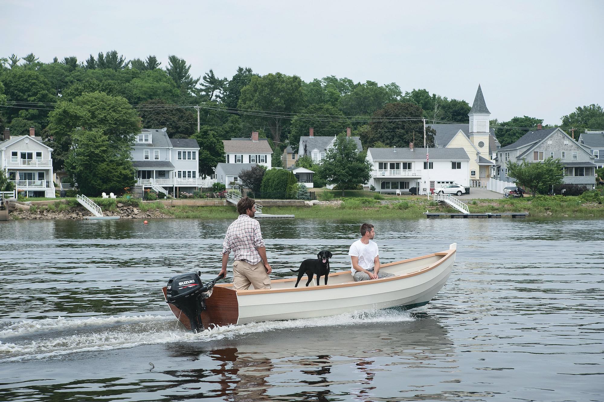
The Amesbury Skiff is a classic outboard-powered workboat derived from the dories of the Massachusetts North Shore. It is also an ideal recreational boat great for exploring, fishing, and family outings.
Over the course of 80 years, the Amesbury Skiff from Lowell’s Boat Shop in Amesbury, Massachusetts, earned a reputation for being exceptionally stable, seaworthy, and rugged. These boats and their ancestors were used commercially for livery, fishing, and rescue work. In more recent years the Amesbury Skiff has proven to be an ideal and extremely versatile family boat. With two side seats in the stern and two thwarts near amidships, these skiffs are comfortable and capacious. The one we’ll build on the following pages is a basic tiller steered outboard version, but a control console could be added for wheel steer-ing. Lockers could also be added under the stern seats. Amesbury Skiffs are technically and historically “dory skiffs” that is, they’re lapstrake planked flat bottomed boats with bottom planking running fore-and-aft.
The Amesbury Skiff as it is known today evolved from round sided, narrow sterned forebears. Around the turn of the 20th century, builders began fitting dories with newfangled one cylinder make-and-break engines. The resultant power dories were great for their times, but the heavy engines caused their fine sterns to squat. The cure was a wider bottom at the transom a solution that gave rise to the boat type we’ll build here. Today at Lowell’s Boat Shop, we build Amesbury Skiffs with stem and frame patterns labeled “O.B. Skiff.” These patterns are nearly identical to those for our round sided Surf Dory.
Given the similarities in the shapes of the frames and stems of the two boats, it is clear that the Amesbury Skiff evolved from the Surf Dory model, with the most obvious change being the shape of the bottom to a “flatiron” form.
 Bob Barton
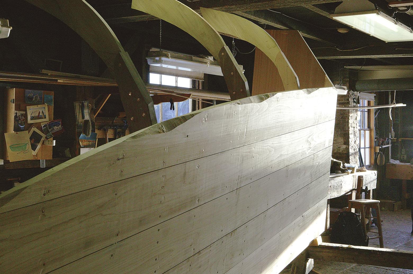
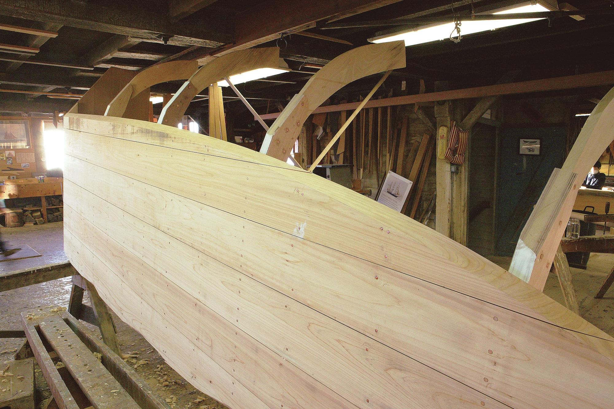
This skiff was built of solid wood—save for the plywood garboards. The construction is simple and strong, requiring no lofting or temporary building jig.
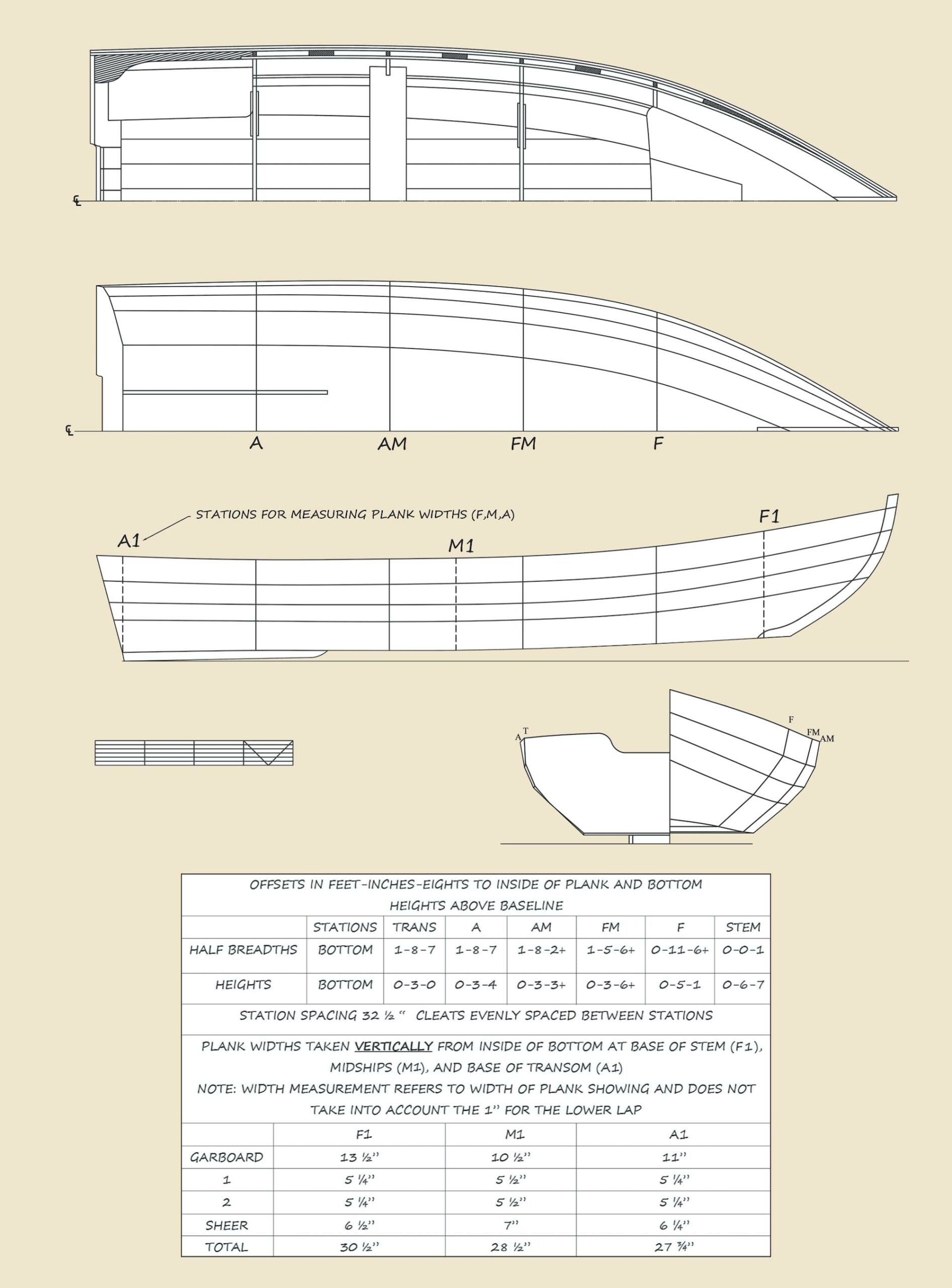
The construction of these skiffs is out of the ordinary. They were designed (perhaps that’s too strong of a word, for they actually evolved) to be built quickly and to be forgiving of irregularities in construction. As such, there is no lofting required. The construction of boats at Lowell’s is detailed in a single sheet of notes giving a few measurements for the bottom shape, which patterns to use for the frames and stem, rough transom measurements, bottom rocker, and plank lining.
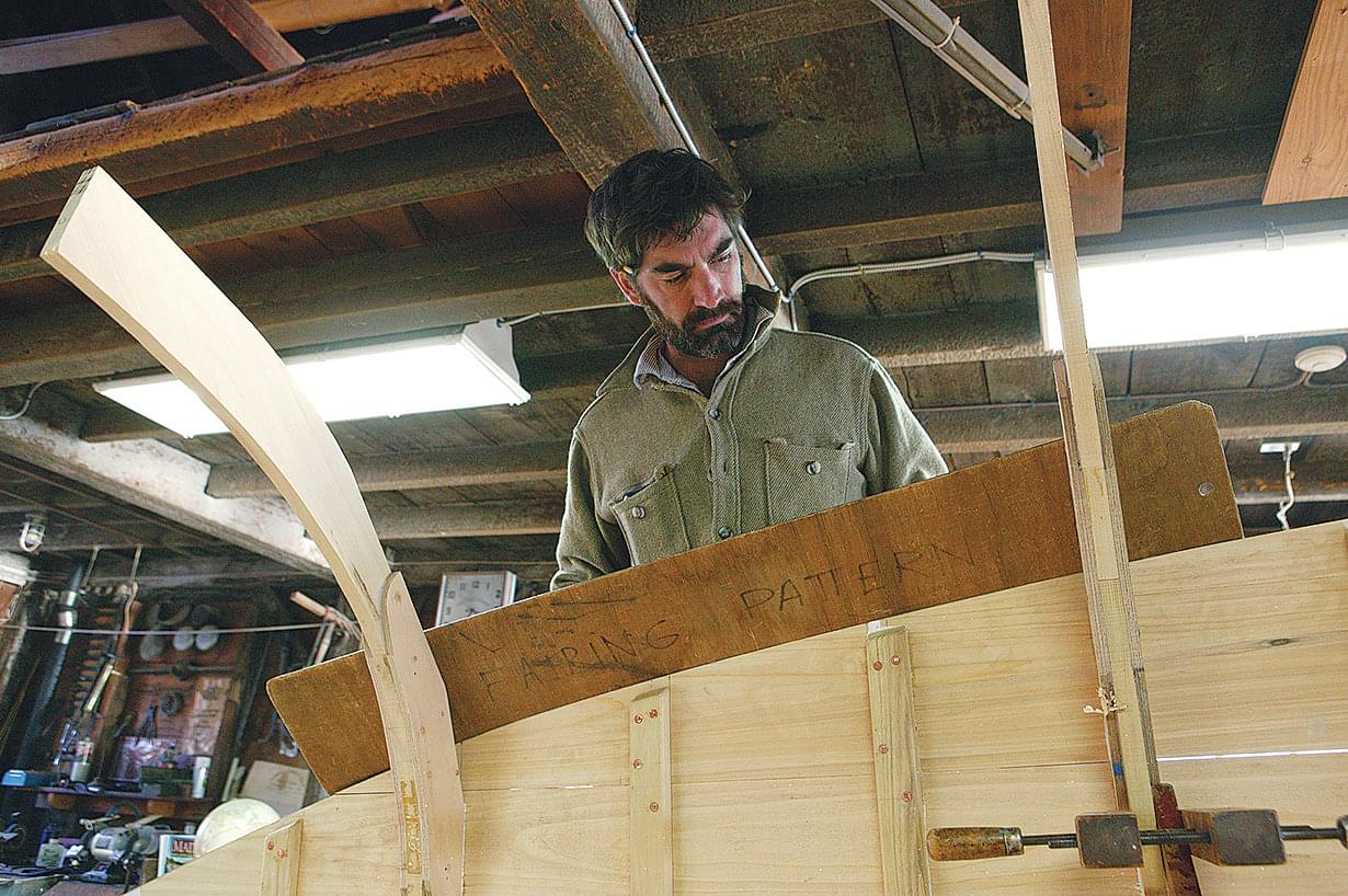
Frames and transom are cut larger than their finished forms and are trimmed as the planking progresses. Some notes exist for seat placement and finishing touches; however, rail and breasthook construction, and a multitude of other details, are understood to be pretty standard. Since you don’t have access to our patterns, I have developed the drawings shown here, based on the age old patterns that we still use at Lowell’s Boat Shop. While dory and dory skiff construction is basic and forgiving, one should take care with every step. I believe that the best available reference for the construction of these types of boats is The Dory Book, by John Gardner, and I’d advise having a copy of it handy if you embark on building one of these boats.
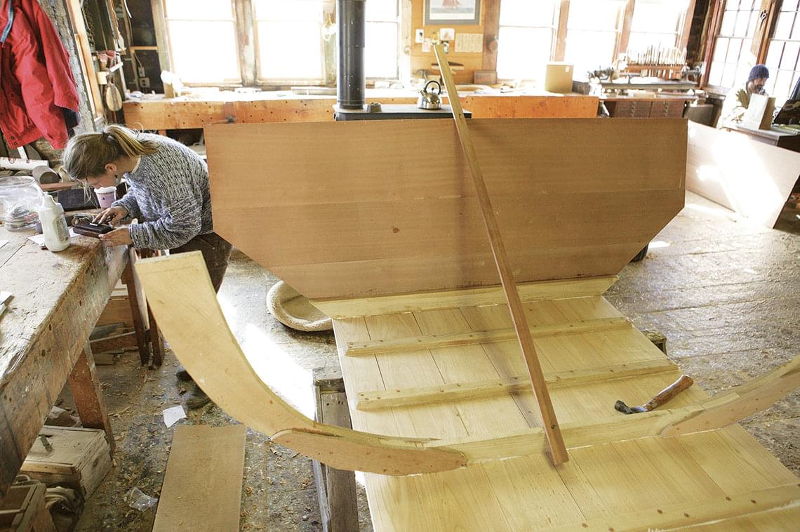
The book’s only omission is a description of how to cut a dory lap a process I’ll explain in Part 2 of this series. If you get hung up on the dory lap, or any other part of the construction, please know that Lowell’s is as much a teaching institution as it is a museum and working boatshop. We are happy to answer specific questions for anyone undertaking dory projects of their own. (Our contact details appear at the end of each installment of this series.) Construction begins with the skillet, which, in dory parlance, is the assembled bottom, with frames, stem, and transom attached; the resulting frame is said to look like a spider skillet a three legged cast iron pan used for cooking over an open fire. Assembling the skillet requires a series of steps, the first of which is to lay out the bottom.
Bottom
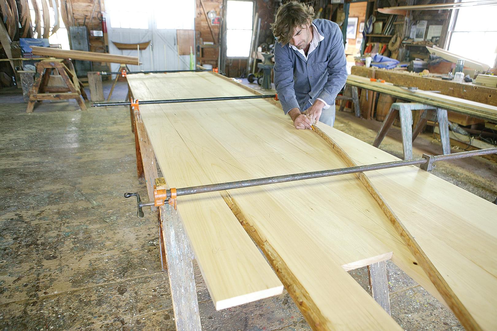
The maximum width of the bottom is 413⁄4″. I make up the bottom blank of 7 ⁄8″ cedar or heart white pine planks in widths between 5″ and 8″. Traditionally, wider planks would have been used, but wider planks, because they shrink and swell more than narrow ones, cause the plank seams to open up unacceptably when the boat is out of the water. Join the planks so the seams between them are tight, reserving the widest planks for the outboard locations. Clamp the planks together and lay out the bottom shape before planing their edges for caulking seams; otherwise the planks will tend to buckle when clamped together from below with pipe clamps.
–
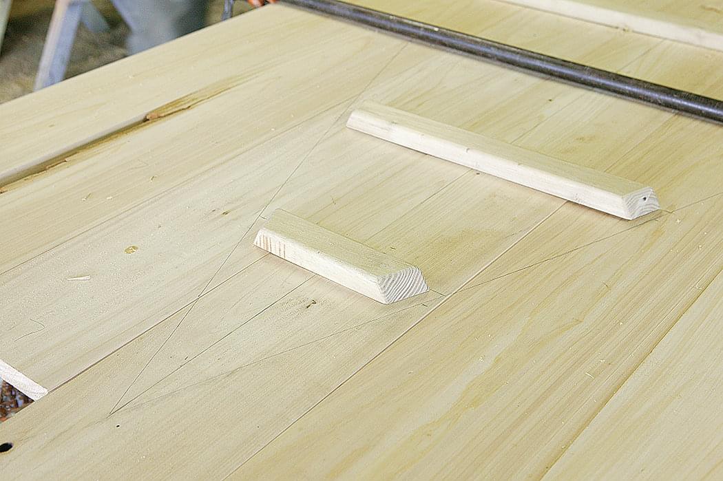
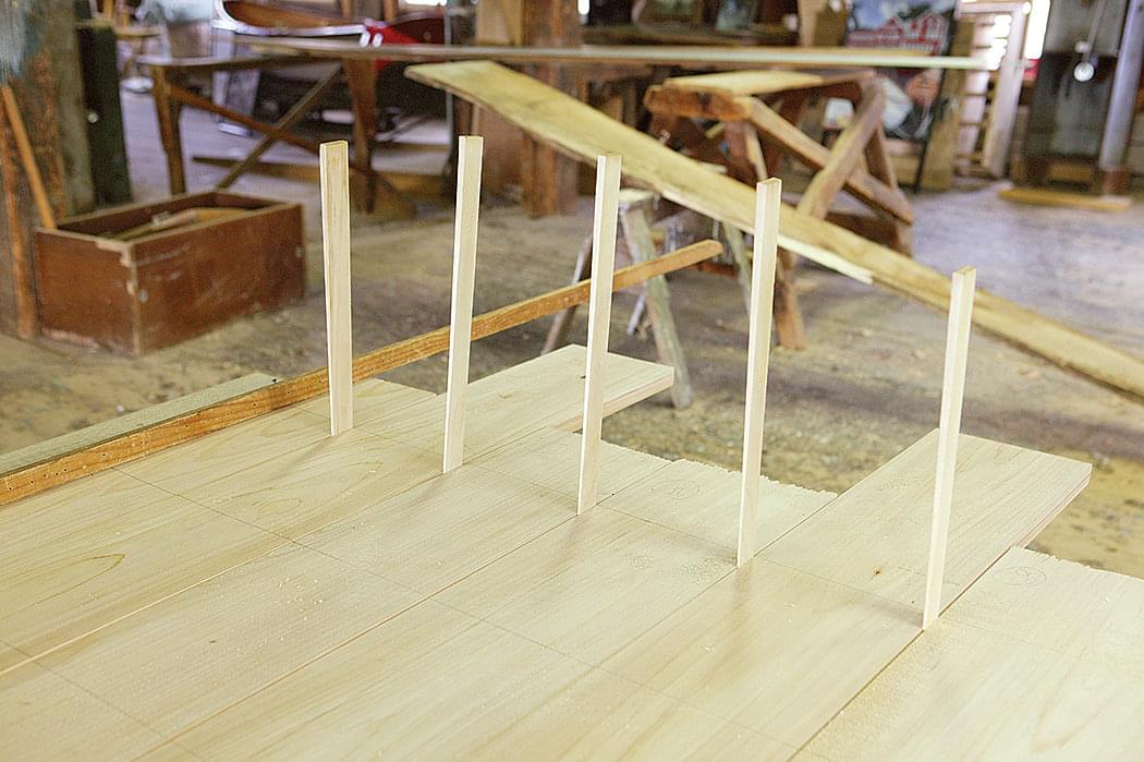
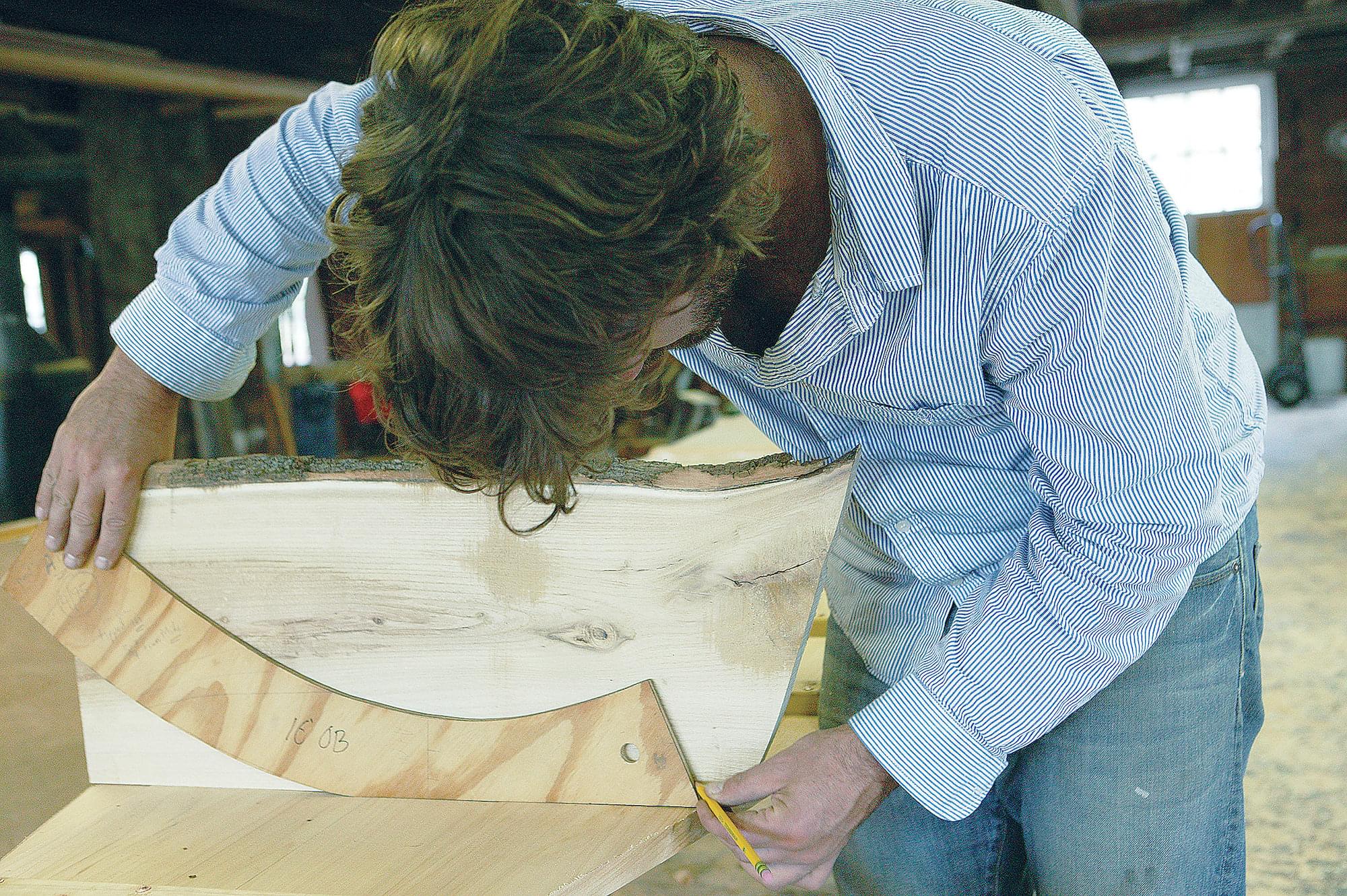
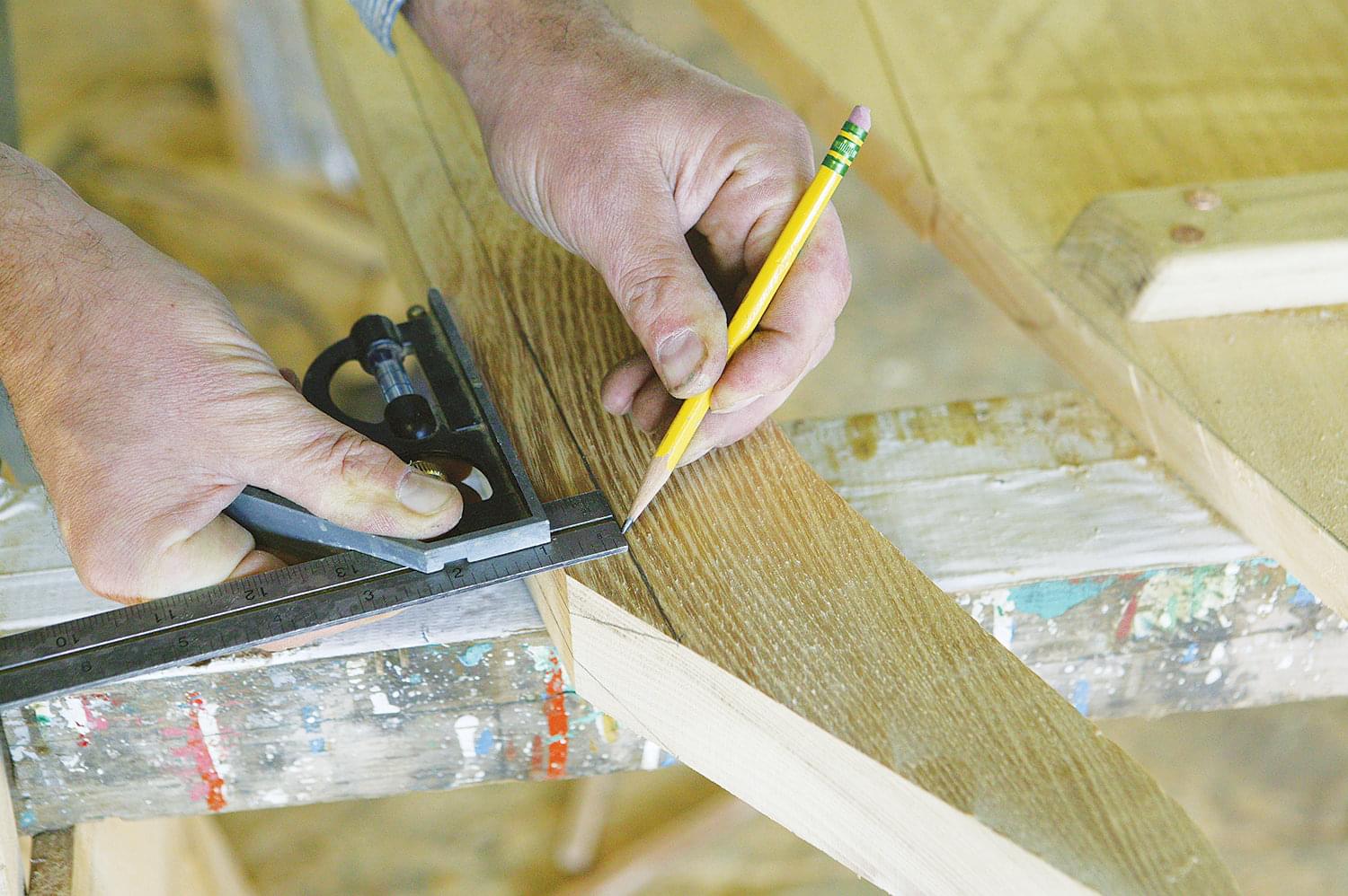
To lay out the bottom shape, first draw a centerline, leaving enough stock on either side for the maximum half-breadth. Avoid having a plank seam on the centerline, as this will cause a weak site for fastening the stem and the joint will eventually leak. Once you have a centerline, lay out frame stations at right angles to it, and mark their half-breadths. Next, bend a batten in a fair curve around the half-breadth marks and draw the outline of the bottom. Resist the urge to cut out the bottom at this stage as you’re about to take it apart briefly, and cutting it now will make it a bear to clamp back together.
–
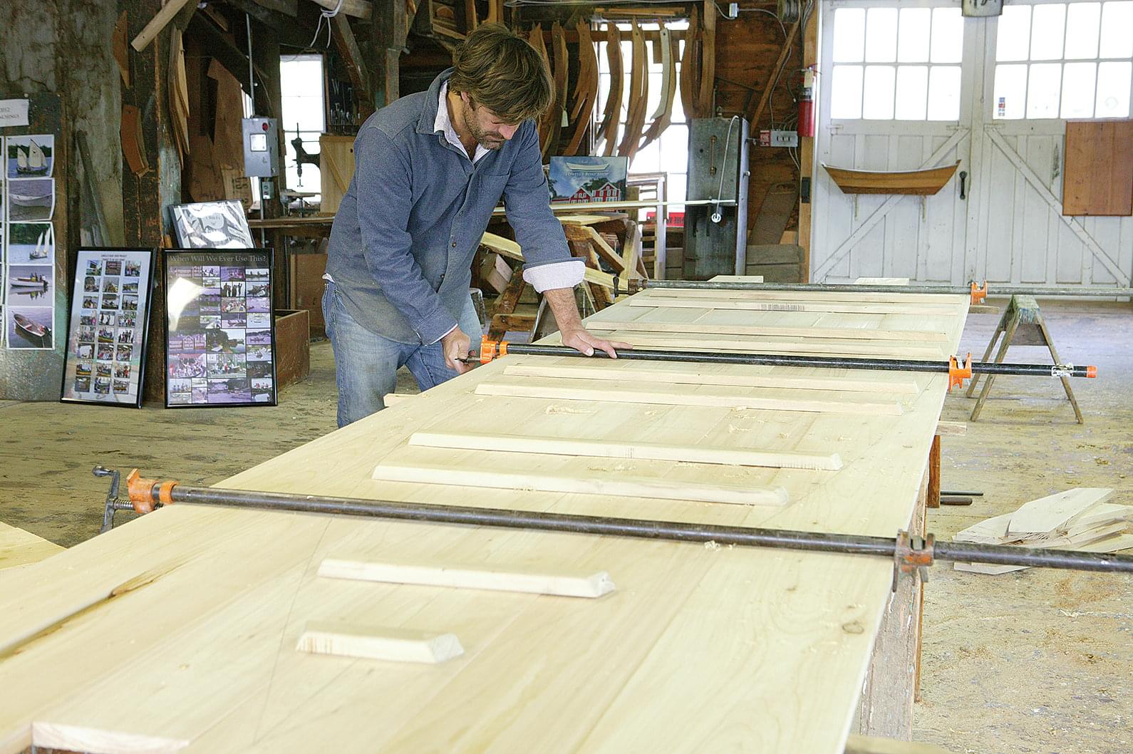
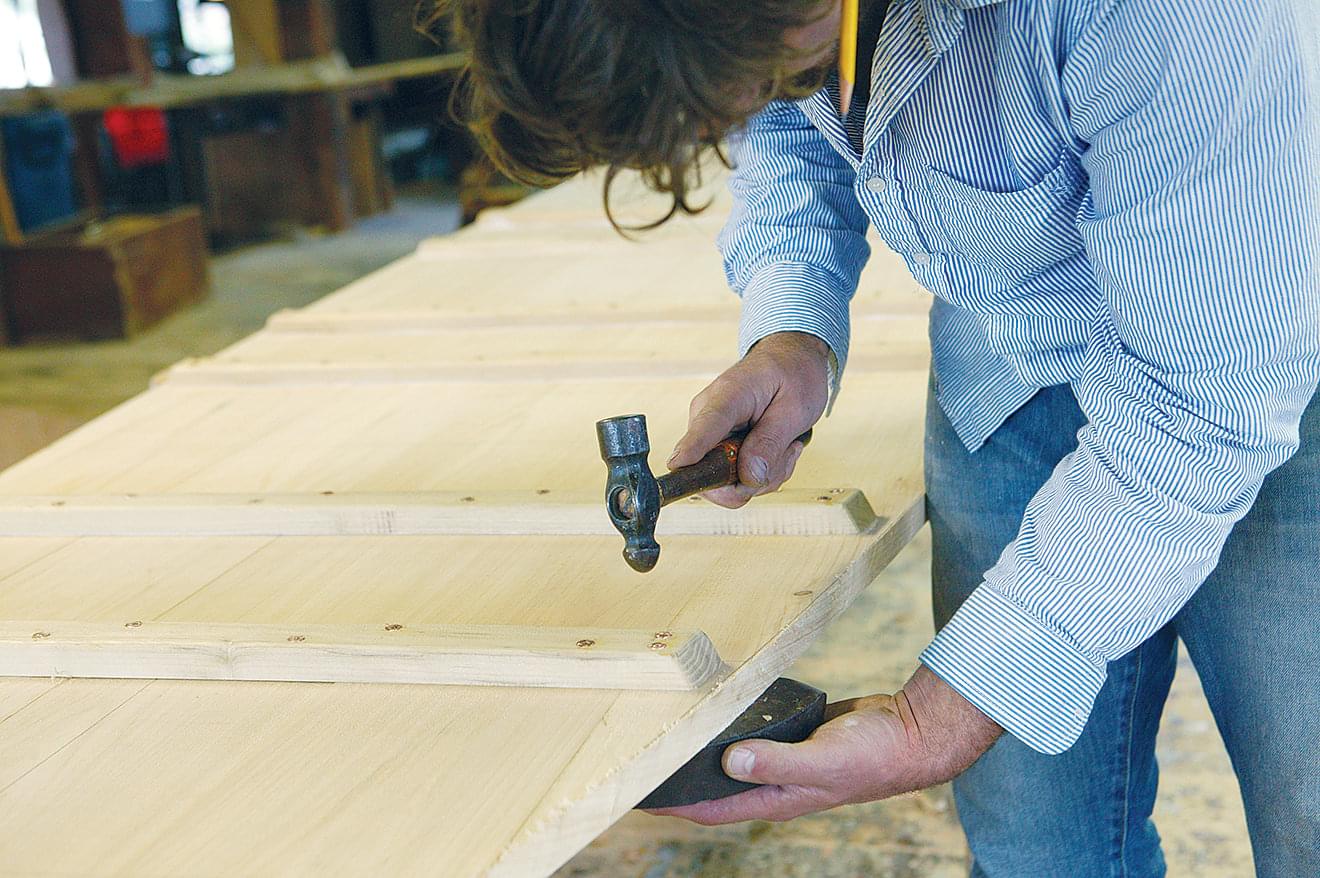
Now that you have the bottom outline marked, it’s time to lay out the cleats that go between the frame stations to hold the bottom planks together. Divide the distance between frame stations into three equal parts; this will give you spacing for two cleats between each frame. Cleats are typically 7⁄8″×2″ oak, or leftover bottom stock, riveted through the bottom—although one can also use screws. To make the cleats, rip up some stock in lengths longer than the bottom is wide at each cleat station. Lay the stock directly on the bottom and center it over the cleat station.
At each cleat station, mark the cleats an inch shorter than the bottom is wide. Cut the cleats to length and dress them as you see fit. I recommend laying them on the shop floor and walking on them with your bare feet; this will give you an idea of how much you want to round their corners and sand them.
–
Before permanently installing the cleats, take the clamps off the bottom, disassemble it, and mark and cut a 1⁄16″ caulking bevel on one edge of each plank. Then clamp the bottom back together, this time with the bar clamps on the inside of the bottom, as the planks will be less likely to buckle this way. As you clamp, you should use shims to create gaps of about 1⁄8″ between the planks at the transom. This gap will allow the bottom planks to swell without pushing the garboards away from the transom. Now you can fasten your cleats to the bottom, making sure to bed them in paint or in whatever concoction you prefer.
–
–
With the cleats now holding the planks together, remove the clamps and cut out the bottom, making sure not to get inside of the line you drew. It saves some time later if you cut the bottom at the transom to the angle of transom rake, which is 14 degrees. Finish by planing the edges of the bottom down to the line, but not beyond it.
Caulking Seams
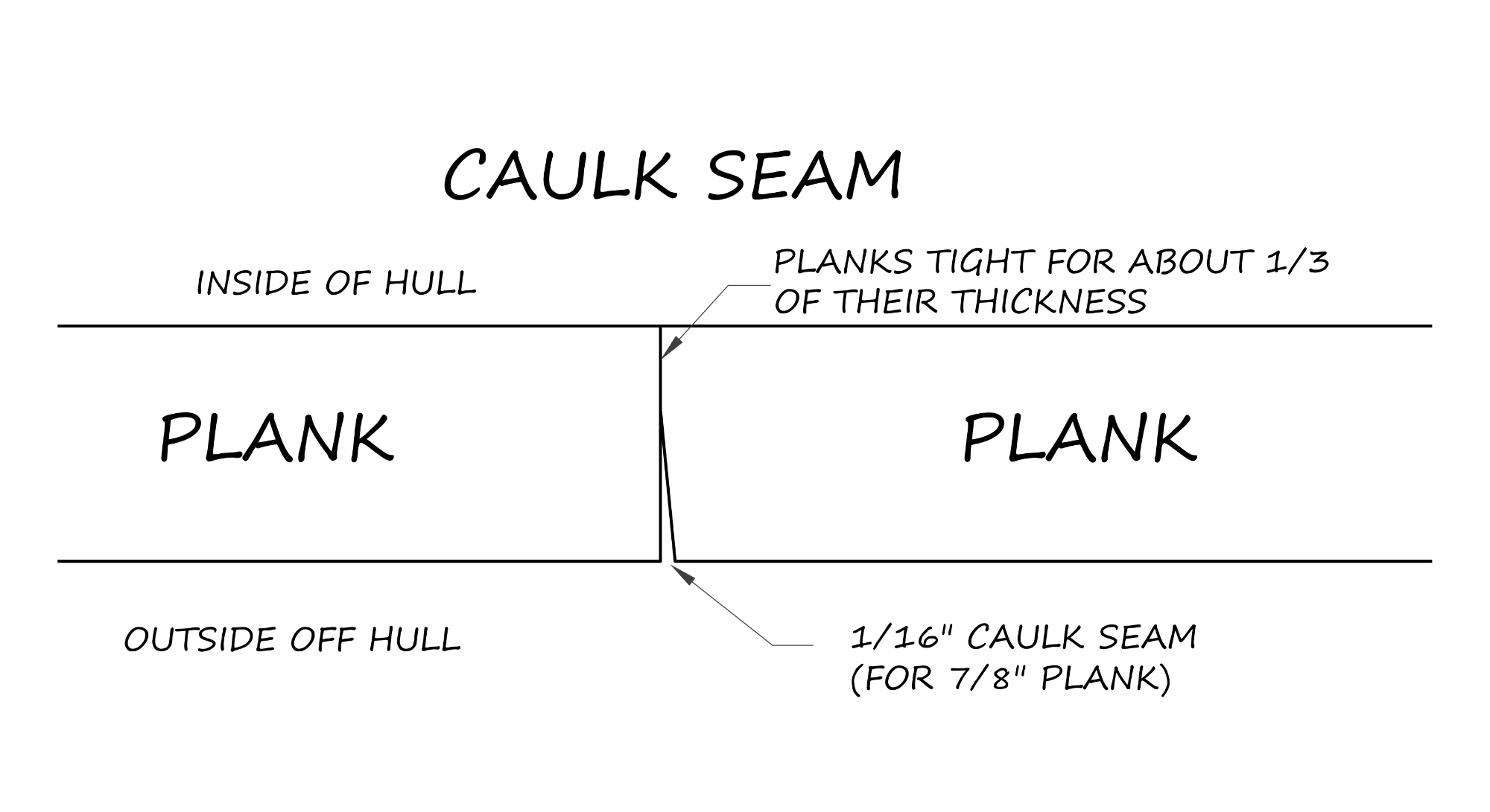
Caulking seams are wedge-shaped gaps between planks that allow for caulking material to be driven between planks to make a hull watertight. As with most boat building tasks, if you ask five boatbuilders how to lay out and cut these seams, you’ll get five different answers. John Tohancyn first had me cut caulking seams while planking a schooner with 21⁄2″ planking; those seams were nearly big enough to drive 3⁄8″ line into, and we cut them with a power planer.
Caulking seams on small boats such as the Amesbury Skiff are a much more delicate matter: My rule of thumb is to create 1⁄16″ of seam width for every inch of planking thickness. The depth of the seam should be two-thirds of the planking thickness; this provides enough room for caulking and putty, and also leaves the planks touching for one-third of their thickness. While it’s not a concern on the lapstrake-planked Amesbury Skiff, take care with the caulking seams on the topsides of carvel-planked boats; they draw the eye, and thus their quality speaks for the quality of the boat. The seams on the bottom of the Amesbury Skiff are a good place to gain skill and confidence in this operation.
Materials List
Wood
Bottom planking: 7⁄8″ white pine or cedar; enough to yield a bottom blank of 46″ × 14′ from 5″-8″-wide boards
Garboards: 1⁄2″ marine plywood; 1 sheet
Topside planking: 5⁄8″ white pine or cedar; approximately 100 linear feet, no narrower than 10″
Bottom cleats: 7⁄8″ ×2″ white oak or black locust; approximately 30 linear feet
Frames: 7⁄8″ white oak or black locust; 30 linear feet, minimum width of 2″
Frame gussets: ½” marine plywood; offcuts from garboards
Stem: 17⁄8″ white oak or black locust; dimensioned per drawings
Transom: 7⁄8″ white oak or mahogany; enough to yield a rough blank of 26″ × 60″
Fashion pieces: 7⁄8″ × 10″ white oak or black locust; 6 linear feet
Inwale: 5⁄8″ ×15⁄8″ white oak; 16 linear feet, 2 required
Outwale: 5⁄8″ ×15⁄8″ white oak; 18 linear feet, 2 required
Breasthook: 1½” white oak, mahogany, or black locust; enough to yield a blank of 8″ × 12″
Transom pad: 7⁄8″ white oak or black locust; 20″ × 26″
Quarter knees: 1½” white oak or black locust; enough to yield two blanks of 8″ × 42″
Seats and thwarts: 7⁄8″ pine, cedar, or mahogany; minimum width of 10″, see drawing for lengths
Skegs: 7⁄8″ ×3″ white oak; 9 linear feet
False stem: 17⁄8″ × 5⁄8″ white oak; 4 linear feet
Risers: 5⁄8″ ×3″ white pine or cedar; 2 pieces of 12 linear feet.
Fastenings and Glue
Frames to bottom, hood ends at transom, laps at frames, transom to bottom: 2″ No. 10
silicon-bronze ring nails; 2 lbs
Garboard to bottom: 2½” No. 10 silicon-bronze ring nails; 2 lbs
Hood ends at stem, inwale, false stem: 1½” No. 10 silicon-bronze ring nails; 1 lb
Bottom cleats, frame gussets: 2″ No. 10 copper rivets; approximately 2 lbs
Plank laps: 1½” No. 10 copper rivets; 4 lbs
Rails: 3½” No. 10 copper rivets; ½ lb
Fashion pieces, transom scab, seat risers, seats, miscellaneous items: 1½” No. 10 silicon-bronze wood screws; 1 box
Rails, skegs, miscellaneous items: 2″ No. 10 silicon-bronze wood screws; ½ box
Transom knees: 3″ No. 12 silicon-bronze wood screws
Epoxy: approximately 1 quart (unless epoxy coating the bottom and garboard, in which case 1 gallon)
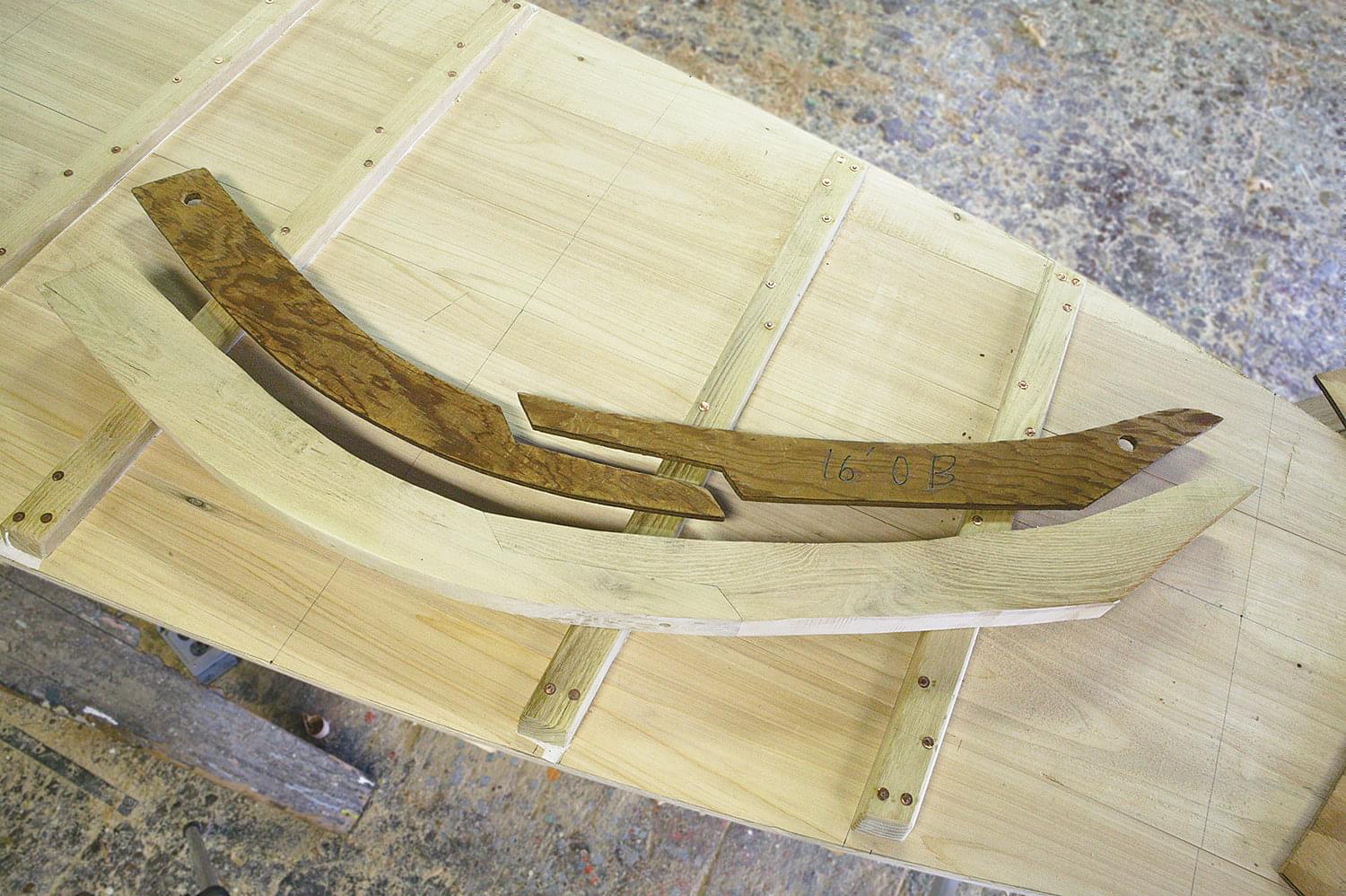
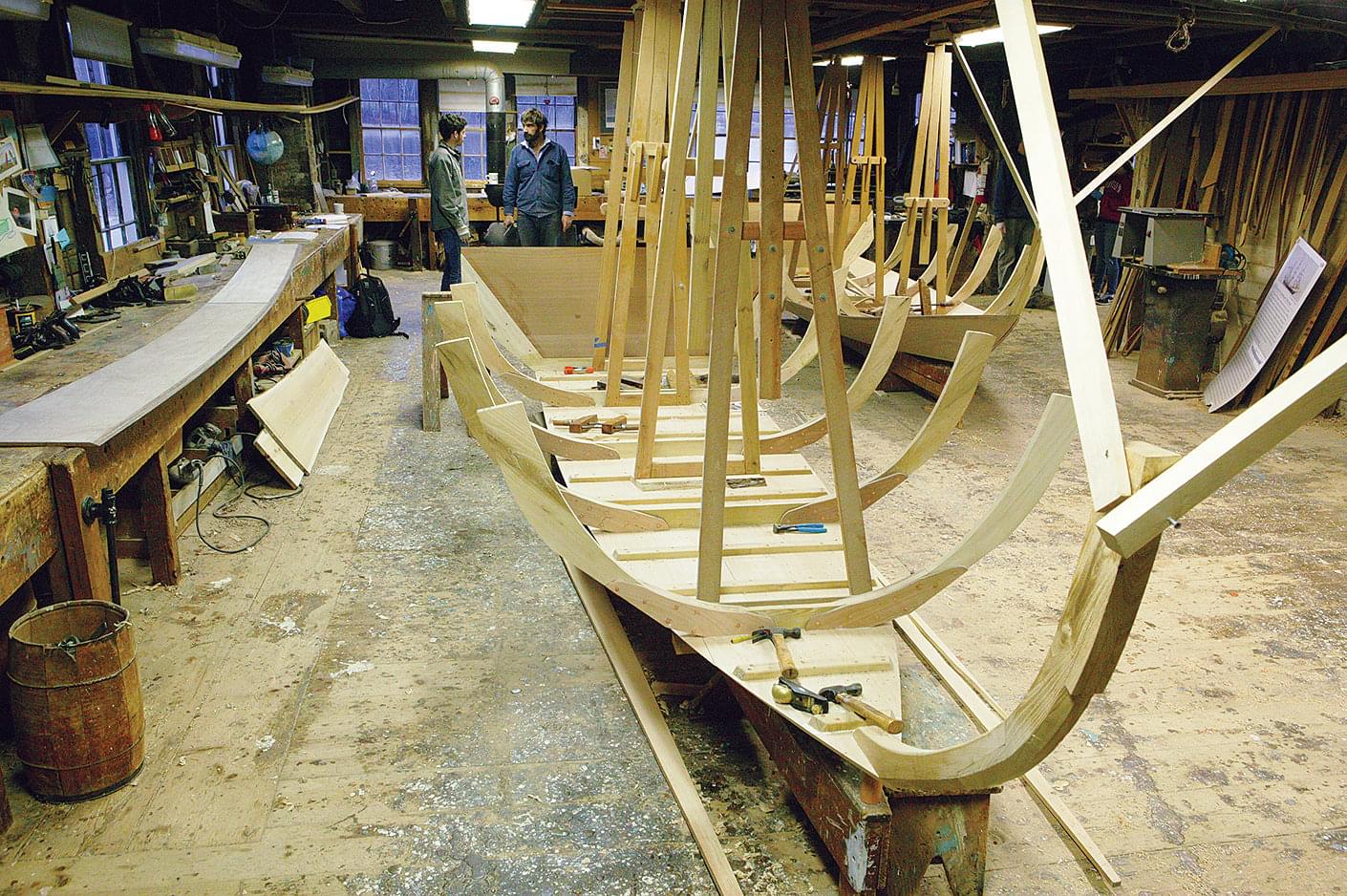
Frames
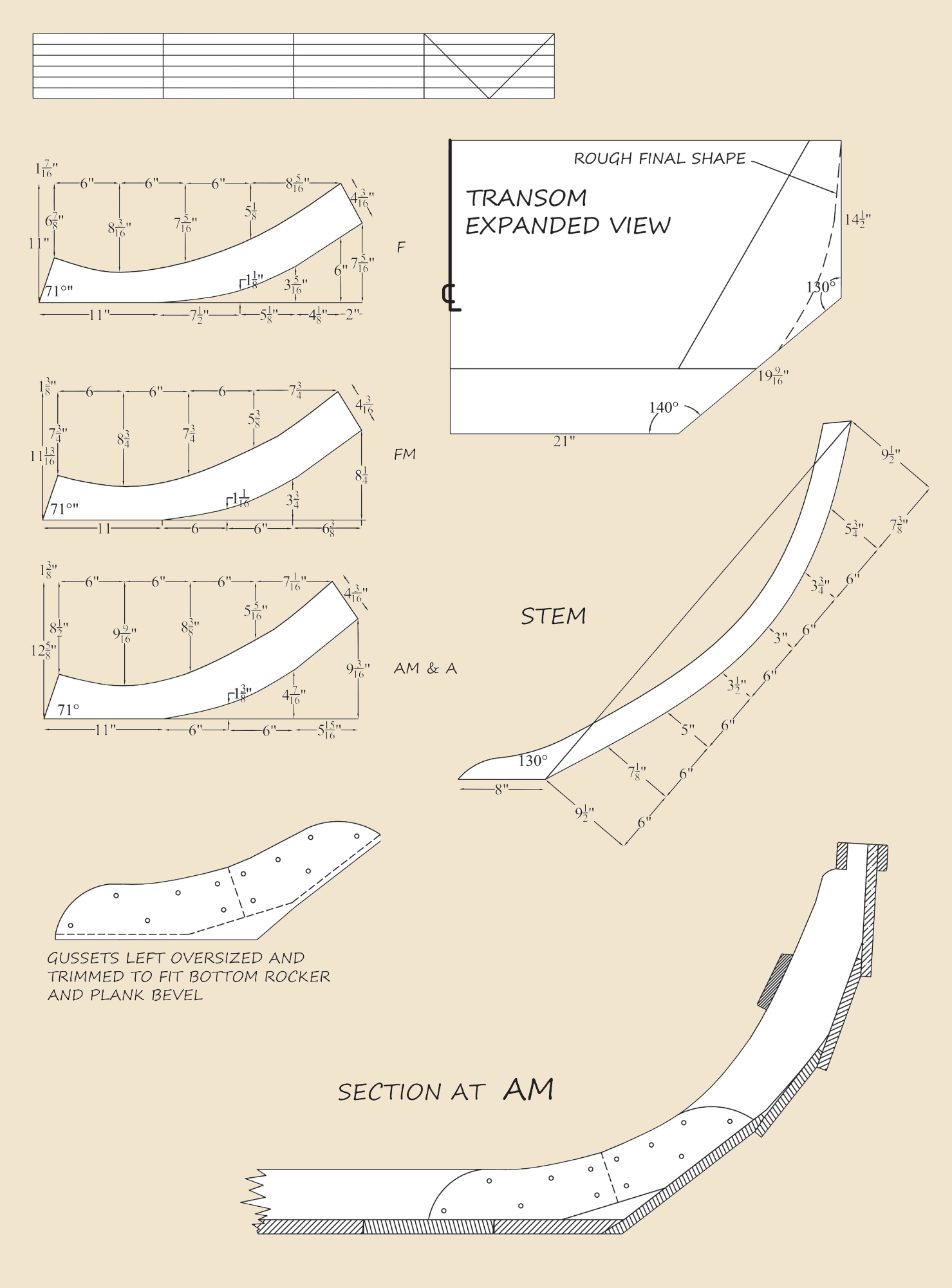
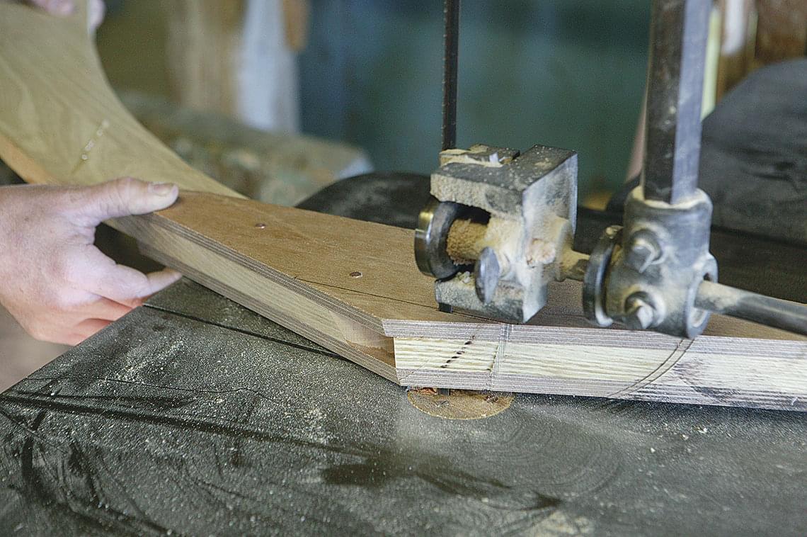
With the bottom complete, it’s time to make the frames. These are made of 7⁄8″ white oak or black locust in three pieces, consisting of two upper frames and a floor timber, joined together by plywood or oak gussets. At Low- ell’s Boat Shop, there are patterns for the upper frame pieces; however, their shapes can also be determined by using the drawings on page 75. The pieces are joined with a miter at the chine. Floor timber lengths can be measured right off of the bottom at each frame station, keeping in mind that they’ll need to be beveled, or “dubbed,” for the planks.
To account for frame beveling, measure the lengths of the floors 3⁄8″ aft of each frame station’s centerline; the resulting extra length will leave plenty of stock for this operation. When laying out the upper frame pieces, it is best to find stock that has a natural sweep that conforms to the hull’s curved sections. (I have a stockpile of black locust with the appropriate sweep, but it’s hard to come by, so I have hidden it in a safe place.)
–
The frames can also be gotten out of 10″- to 12″-wide oak planks laid out such that the lower part of the frame runs parallel to the grain of the wood. If you take this approach, don’t expect your frames to be free of grain runout at their tops. I also have had luck utilizing the bell of live-edge oak, or the natural bend in the grain around large knots. When assembling the frames, make sure you correctly match the floor timbers and upper frame pieces with their individual stations—marked Forward (F), Forward Middle (FM), Aft Middle (AM), and Aft (A).
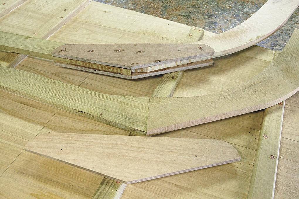
Before you curse me for poor draftsmanship, please know that the gussets you see in the photograph are oversized to allow for beveling; much of the excess we see here will be removed before the frames are attached to the bottom. I bed the gussets in epoxy to add strength and to seal the end-grain of the frame pieces at the miter before fastening the whole sandwich together with copper rivets. The result of this operation should be four complete frame assemblies, one for each of the four frame stations. The underside of the forward frame assembly receives a 4-degree bevel so it angles forward by that amount; the forward middle frame gets a 2-degree bevel; and the after two frames are set up vertically.
–
The forward angles of the two forward frames allow them to stand plumb when the rocker is sprung into the bottom. Set up each frame assembly at its station and trace on its underside the outline of the bottom (essentially a short, straight line). At the same time, trace the frame floors onto the inner. Bevel the lower portion of the frames to the angle you traced off the bottom to allow the garboard planks to lie fair on each frame. Before fastening, cut the chine corner off each frame to provide a limber hole.
–
To fasten the frame assemblies, use the tracings of the frames to locate 1⁄8″ holes drilled from the inside out. This will mark the hole locations on the outside, allowing you to drill the proper 1⁄8″ holes from the out- side, through the bottom, and into each frame assem- bly. Paint the mating surfaces and then clamp the frame assemblies in place one at a time. Fasten them with 2″ 10d bronze ring nails spaced about 2″ apart.
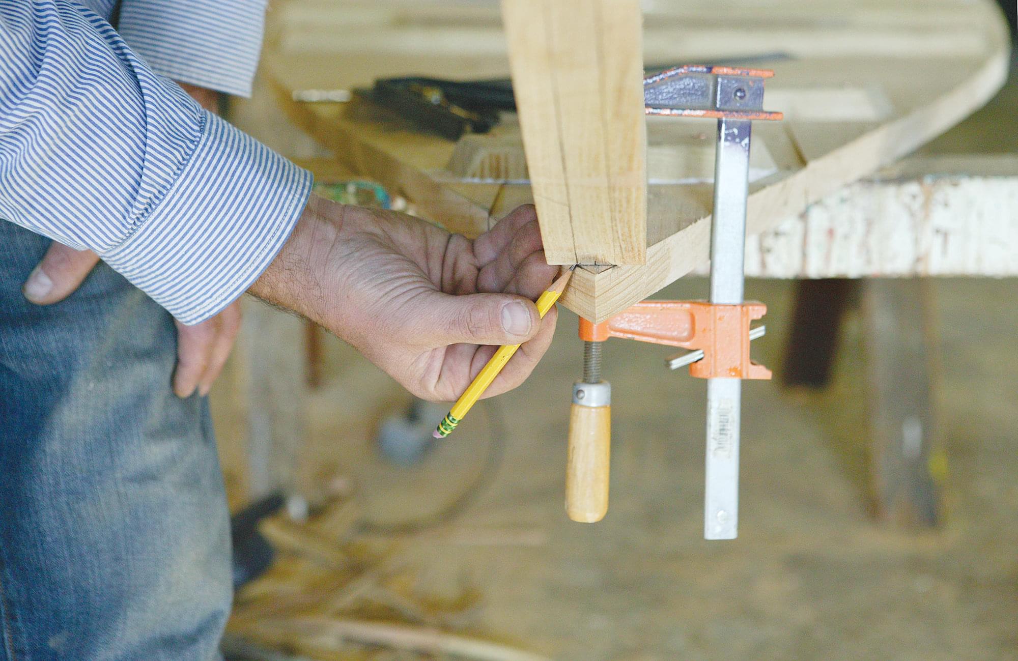
The stem is fashioned out of 17⁄8″ white oak or black locust. Its shape requires a scarf about halfway up, put together with epoxy and screws. The screws are Stem positioned at each end of the scarf, two on the interior face, and a single one on the exterior face right on the centerline so it will clear the stem bevel.
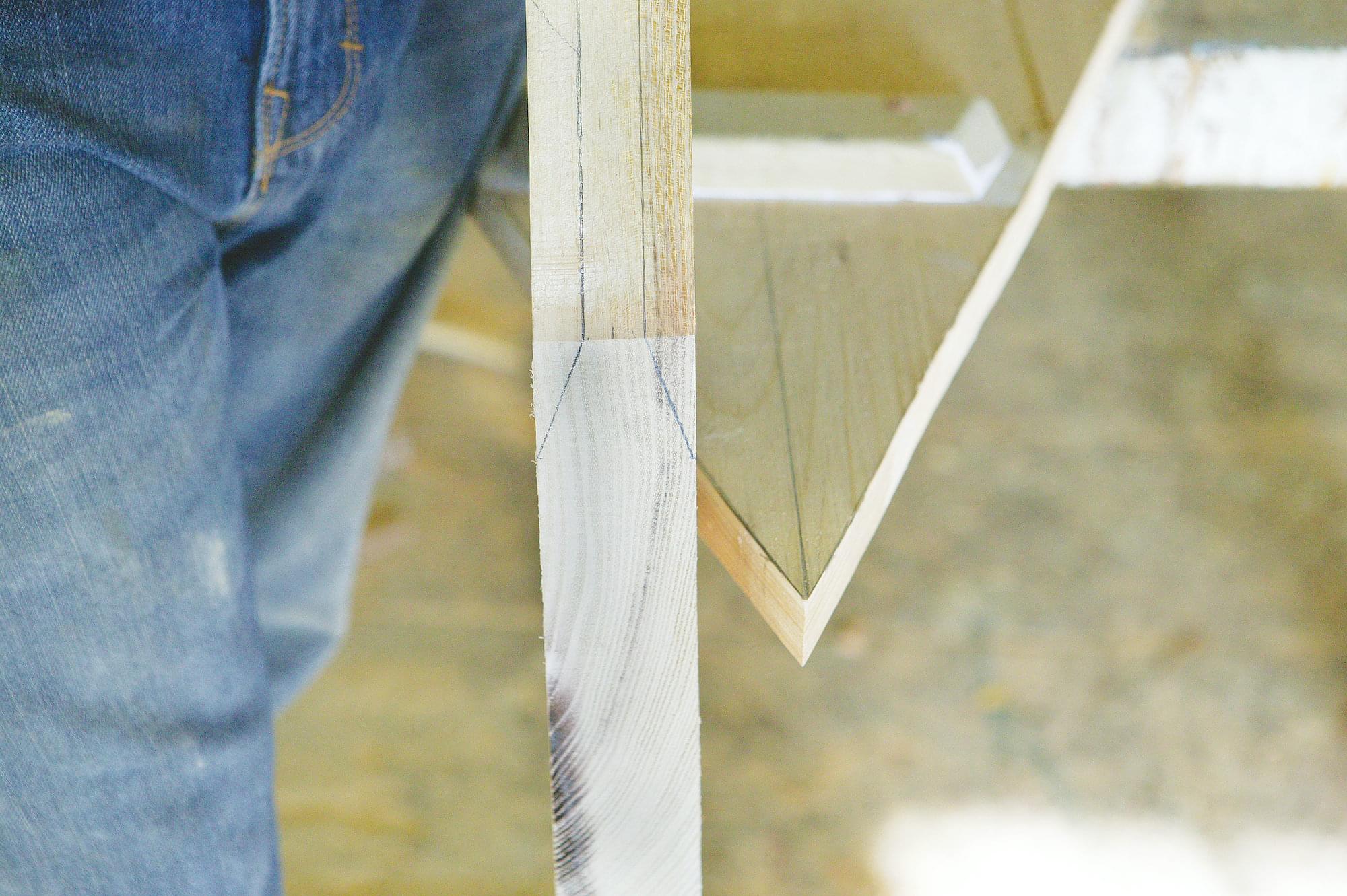
The initial stem bevel is determined from the bottom shape. First, draw two lines on the face of the stem 5⁄8″ in from the edge; this will leave you with a 5⁄8″ space down the middle. Center the stem heel at the bow and clamp it so the lines you just drew on its face just intersect the sides of the bottom. This will leave a small triangular piece of bottom protruding forward of the stem.
–
Now, as you did with the frames, trace the shape of the bottom onto the underside of the stem. Unclamp the stem and mark the point at which the line you just drew on the bottom intersects with the side. From this point, scribe a line on the side of the stem parallel to its face.
–
–
Using these lines as guides, bevel the bottom 38″ of the stem. This rough bevel will be adjusted as you plank, and the upper stem will be fine-tuned when the sheer plank is ready to fasten. Bed the stem in your choice of bedding and fasten it with two 2″ ring nails and two copper rivets through the toe.
–
–
Transform
The transom is made up of two or three pieces of edge joined mahogany or oak. The rough dimensions for the transom blank are 26″ × 60″. I used to simply edge-glue the pieces together with epoxy and depend on the various backing pieces added later to hold the whole works securely. Since then, we acquired a tongue-and-groove router-bit set at the shop, so I now put them together
with epoxy and tongue-and-groove joints; this adds a little strength, especially when using oak, which doesn’t take epoxy well.
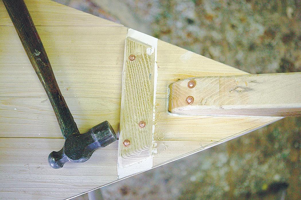
It also helps with alignment. The base of the transom sits on the bottom and is beveled at 14 degrees to give the transom the appropriate rake. A hardwood cleat is attached at the inside bottom of the transom for strength and added nailing surface.
–
So-called “fashion pieces” are also added to the sides of the transom to provide more backing for nailing and to help hold the transom together. Bed the bottom of the transom, keeping in mind that this is a well-stressed joint; fasten it with 2″ ring nails or screws.
Bottom Bevel
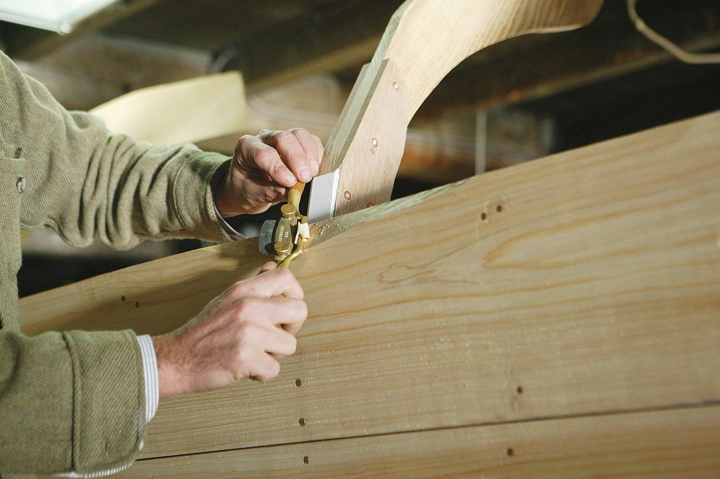
With the skillet complete, it is now time to bevel the bottom to accept the garboard. The watertight nature of this joint depends entirely on the evenness of the bevel, so sharpen your plane, take a breath, and take your time. But no pressure! To begin: Tip the skillet so the bottom is vertical, and use some strips of scrap clamped to the frames to prop the whole works up. You will need a drawknife, spokeshave, and straightedge.
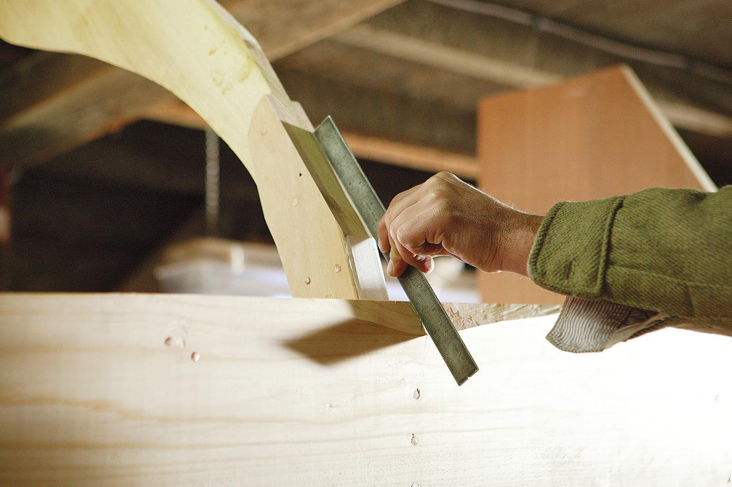
At each frame, scoop out a 6″ or 8″ bevel with the drawknife and fine-tune it with the spokeshave until you’ve brought the inside corner of the bottom to a feather edge, and the straightedge lies flat on both the beveled edge and just off (that is, not contacting) the lower part of the frame. Take one more pass with the spokeshave, focusing on the outside face of the bottom to create a slight gap. The straight edge should now bear ever so slightly on the feather edge and should begin contacting the frame at a point about 6″ up.
–
Don’t be afraid to carry your scooped-out bevels 6″ to 8″ on either side of the frame, as this will make fine-tuning with the spokeshave easier—just make sure the lowest part of your “scoop” does not go deeper than the line of the frame. Use the same process for beveling the bot- tom at the stem and transom; however, at these points, the straightedge should bear against the stem or transom all the way to the feather edge, and there should be a slight opening at the bot- tom of the bevel, as there was at the frames.
The slight gap ensures that the garboard and bottom are in contact with each other all along the feather edge; the beveled edge of the bottom, upon swelling, will press into the garboard slightly, assuring a watertight joint. This joint will not be caulked, as it’s full of nails and the caulking risks pushing the garboards away from the bottom board.
–
With the initial beveling complete at each frame as well as at the stem and transom, the edge of the bot- tom should resemble a landscape of hills and valleys. Using a good batten, connect all the low points of the scooped-out bevels with a fair curve and draw a nice dark pencil line.
I advise students to also run their pencil along the corner at the inside face of the bottom, and to keep that marked corner sacred: If that line disappears, you’ve gone too far.
–
With the bevel thus laid out, you can begin removing the remaining material. The old-timers undertook this bevel without the use of pencil lines; a fairing bat- ten was all they needed, and you will find that you will need one too. A piece of lauan plywood, 12″ wide and 4′ to 5′ long, will serve this purpose well. As you remove material from the edges of the bottom, lay the fairing batten on two frames and along the bottom’s edge in between them as a sort of sample plank to test your fit. (You must, of course, be sure to bevel the frames first.)
–
When you have completed your bevel and can’t see daylight anywhere between the bottom and the fairing batten, the skillet is ready to go down on the build- ing bed. At Lowell’s we have several building beds, or strongbacks, made from a piece of 2×8 the length of the bottom, raised to about 12″ above the floor and leveled as much as can be done in a 150-year-old shop. The building bed will provide a solid foundation on which to build the remainder of the boat and keep it from wracking while bending the side planks.
–
Amesbury Skiffs have what we call reverse rocker. Rocker refers to a fore-and-aft curvature in the bot- tom. On the 16′ Amesbury, the bottom at the bow is 33⁄8″ higher than the ’midship station and from there remains straight to the aftermost station. The bottom then takes a 1⁄2″ dip from the aftermost station to the transom. This bit of “hook” in the bottom profile acts like a trim tab to help get the boat up on a plane.
It also provides a little extra flotation aft to support the weight of the transom-mounted engine. At Lowell’s, I am able to force the bottom down onto the bed with props from the overhead. However, if this is not possible in your own shop, you can use lag screws through the bottom and into the bed, and plug the holes once the boat is complete.
–
The stem and transom should then be made plumb (stem) and level (transom) and braced in any manner available that will keep them that way and not interfere with planking.
Graham McKay is the manager and head boatbuilder at Lowell’s Boat Shop in Amesbury, Massachusetts. He is also a professional captain of traditionally rigged vessels and he holds an MA in Mari- time History and Archaeology from the University of Bristol. Graham lives in Newburyport, Massachusetts.
We strongly suggest that would-be builders purchase full-scale drawings from Lowell’s Boat Shop. The price of the two-sheet set is $60.00. They may be ordered by contacting Lowell’s Boat Shop, 459 Main St., Amesbury, MA 01913; 978–834–0050; www.lowellsboatshop.com. The shop also welcomes calls or e-mails from builders seeking assistance with construction problems.