
 Jim Bostick
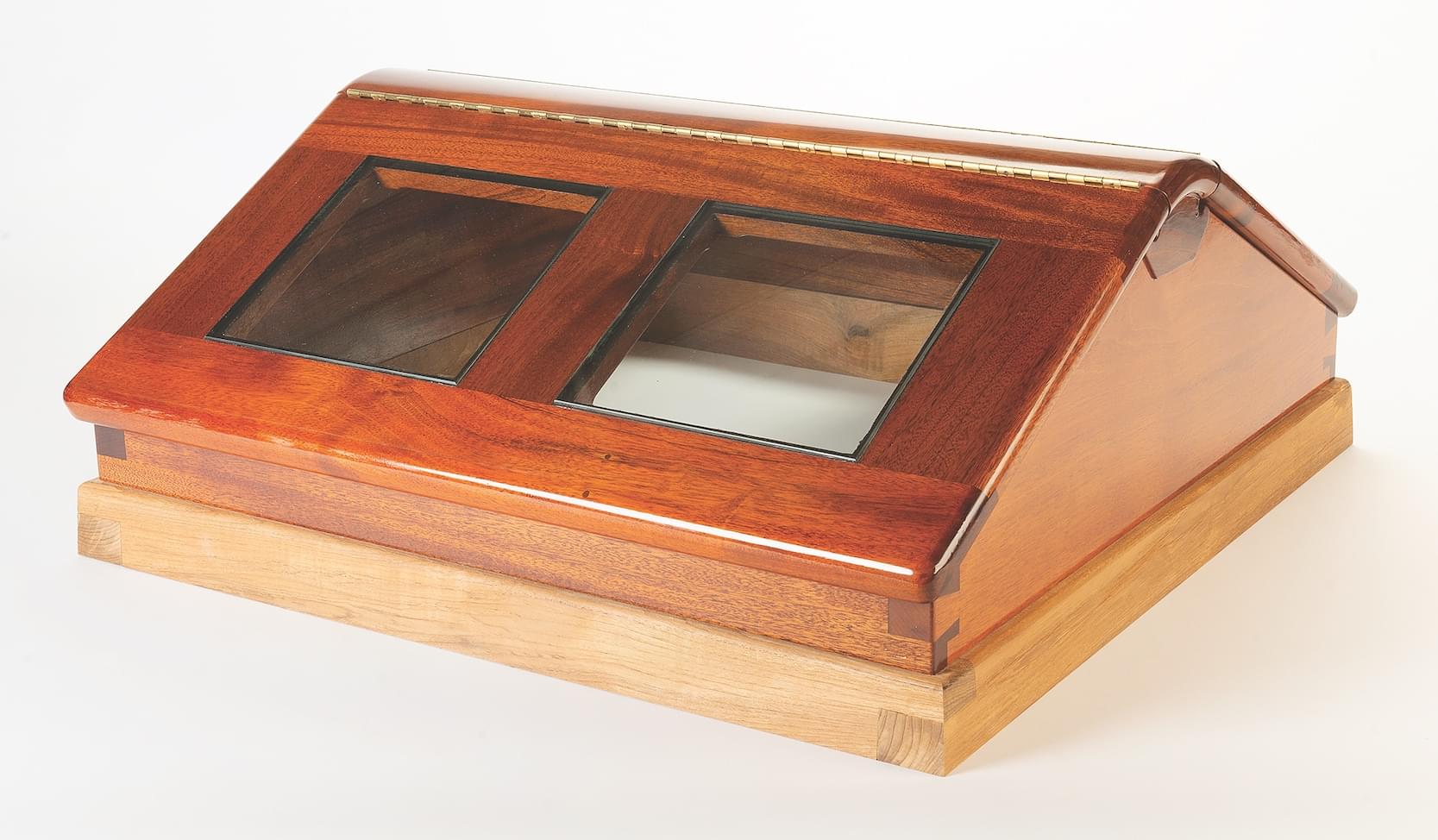
A butterfly skylight is always an elegant addition to a yacht’s fittings. This one, built to a variation by yacht designer Murray Peterson, uses a distinctive curved edge sculpted into the ends of its strongback, or ridge piece, to visually link the sides together.
The skylight whose construction I will describe here originates with Murray Peterson, who gave the essence of simplicity and practicality to every yacht he designed, from its overall shape to details such as those found in this skylight. He developed the original one for the 39′ double ended ketch LILLE DANSKER, which was launched at Hodgdon Brothers in East Boothbay, Maine, in 1947.
As with the booby hatch that I wrote about in 2014 (see WB No. 238), this construction respects Peterson’s original work but has been updated with a couple of tweaks by his son, Bill, a yacht designer in South Bristol, Maine. The principal difference is that Bill called for using rectangular instead of round deadlights. Other than that, this is his father’s design.
A key element is that this skylight’s perimeter is square, and its rabbeted inside lower edges fit over a teak grub, or sill, that is fitted and fastened to the deck. As a result, this skylight can be detached, lifted off, rotated 90 degrees, and reset to catch the breeze regardless of its direction.
“All skylights leak.” This is what I have always been told, and I won’t promise that you’ll never get a drop through this one. But the designer worked very hard to ensure that you will stay dry. The wings swing open on piano hinges, which can be covered with canvas, and below those hinges are brass drip edges that direct any water to gutters shaped into the ridge piece, or what I call the strongback. The undersides of the wings’ side and bottom pieces are grooved to receive rubber gaskets that close onto raised splines let into the frame. You should be snug and dry below.
The feature of this design that most attracted me was the continuation of the smooth, rounded edges of the wing ends across the end of the strongback, forming an arch. It is neat, tidy, and, dare I say, sleek. It is a bit of a chore to make, but why not go the extra mile? It’s for your favorite boat, and you have all winter to enjoy working on the project.
Drawing and Lofting
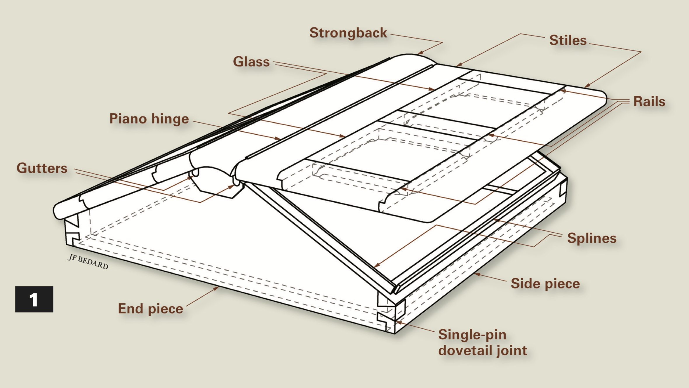
It doesn’t hurt to start with pencil and paper to get a sense of what you are working toward. For those who like to work with CAD renderings, as shown in drawing 1 above, have at it. The precise dimensions and scantlings are ultimately up to the maker, who most likely will not need every tittle and jot itemized but will instead bring a lot of inherent knowledge, a personal eye for proportions, and experience to the project.
After the plan is finalized, a full-sized lofting is essential. Drawing the plan onto a smooth piece of white painted plywood, with the lines knifed into the surface, is what will make you happiest. This gives you something really definite to lay your pieces on when transferring or checking dimensions. Since the wings are sloped, it helps to do a separate, straight-on lofting of them.
This skylight is designed with an inside dimension of 24″, which is plenty. The finished thicknesses are 11⁄8″ for the wings and 11⁄4″ for the frame pieces, so you need to hunt for suitable wood. The height, and thus the slope of the wings, is up to you. I confess that I simply cannot face gluing-up elements for a fine piece of deck furniture such as this, so for me the triangular end pieces had to be made of full-width stock.
I was fortunate to have some short offcuts of Honduras mahogany that were 3⁄8″ wider than the overall height I wanted. But I’m a wood miser, and I have been known to change dimensions to accommodate the timber I have available, so if they had come up 1⁄4″ shy, I would have adjusted the skylight’s height to suit the piece.
For the strongback, I had one last piece of 4″-thick Honduras, but I’ll give you dispensation to laminate one if you can’t find a suitable piece of solid wood. There can be advantages to laminating: because the portions of the strongback beneath its curved ends are cut back and finish about 1⁄8″ proud of the outboard faces of the hatch’s end pieces, making the strongback in two pieces can simplify the work of shaping it. However you choose to plan this, get it right in your drawing, because it will be tricky when it comes time to cut everything and have it all line up.
I am always comfortable with a mix of hand and machine-tool techniques that match my experience and skills to a particular job or that simply make sense. I’ll show some of each. From time to time, I will add asides about simple tricks that work for me. You do what works for you.
The Wings
I chose to build the wings first in case they ended up a dight thicker or thinner than planned, which in turn allowed me to be precise in cutting the rabbet in the strongback into which they fit. I made the wings an eyelash long and initially left their edges square so that I could trim them down later and then round their edges and the strongback’s ends at the same time.
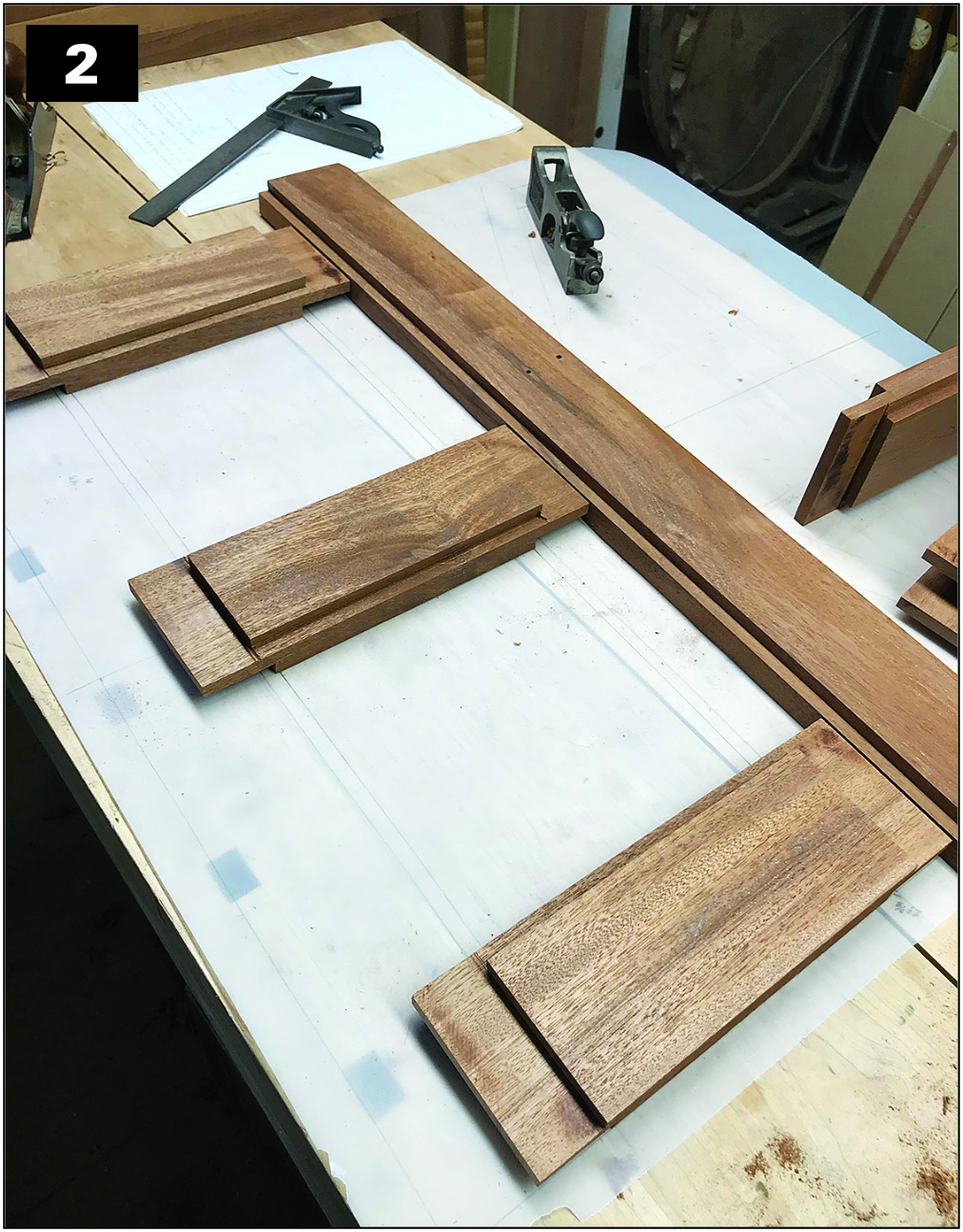
The wings are built like glass-paneled doors, with short vertical rails and long horizontal stiles, as shown in photo 2. Get out the stock, jointed and thicknessed to 11⁄8″, but hold off on hand-planing the pieces until after they are assembled. If you have extra mahogany, it is an excellent idea to get out extra stock to use for trial cuts as you go along, although cheaper wood such as tulip poplar could be used for the purpose. I once made a dreadful mistake on a project and was damned lucky that I had a couple of test pieces that I could just pick up from my bench and use as substitutes.
The rails and stiles are rabbeted to receive 3⁄8″-thick glass panels set in silicone. The rabbets are cut first, on the tablesaw. If you are confident in your technique to get all faces square and then properly smoothed with a rabbet plane, go for it, but remember: any deep or over-cuts by the saw blade will show on the outside at the ends of the joints, and any tipping of the rabbet plane will leave a gap at the surface. If you are nervous about this, cut the rabbet just shy of both surfaces, and finish with a straight bit on the router or shaper table.
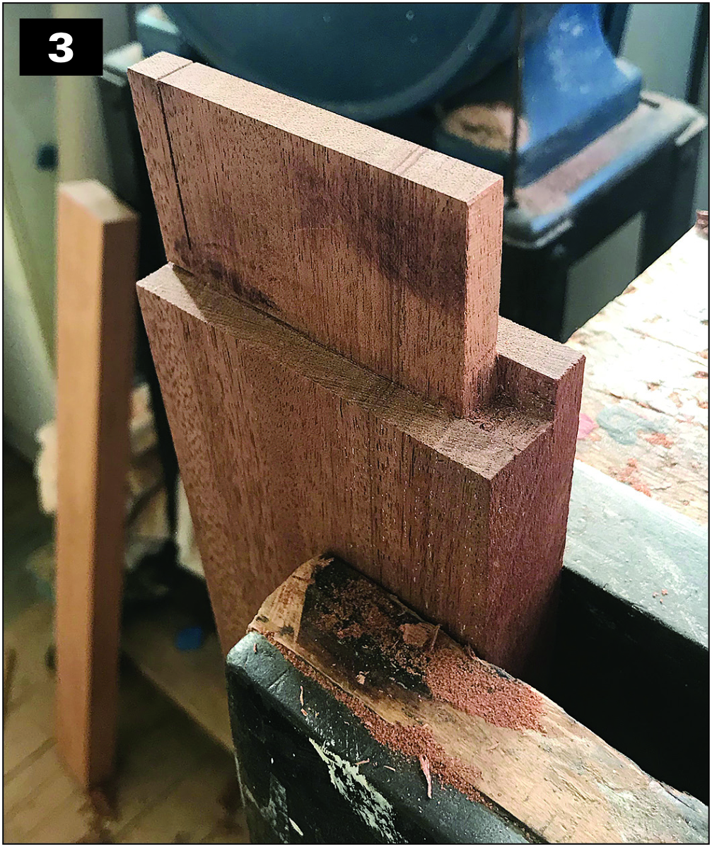
Because of these rabbets, the tenon shoulders and mortise faces must be offset, so lay out the cuts on your stock to be sure that all will fit together properly. This includes the width of the tenons that you will transfer to the end-grain so the line doesn’t get lost when cutting. These tenons are a form of “haunched” tenon, as shown in the rail in photo 3.
In a typical haunched tenon, a short, stepped portion of the tenon extends into a corresponding shallow groove adjacent to the mortise. In this skylight, extensions of the offset tenon shoulders, rather than the tenon itself, fit into the open rabbets in the corresponding edges of the stiles. Note that photo 2 shows that the end rails have a rabbet for the glass only on one edge; the central rail is rabbeted on both edges. The haunches match the width of the rabbet on the inside of the openings, but on the outside edges they are made an extra 1⁄4″ wide to leave plenty of strength in the end-grain of the stiles.
Your drawing will make laying out and cutting the tenon shoulders on the rails and corresponding mortises on the stiles a simple exercise in geometry. Just keep everything on center and square, and you will be fine. Use a variety of colored pencils to highlight the interfaces of the joints on your lofting to simplify visualization and the transfer of the lines to the rails and then to the stiles.
First, cut the cheeks of the tenons vertically against the tablesaw fence using your preferred method probably a saw sled or tenoning jig—to make sure the rail stays square to the blade. Follow by cutting the offset ” deep, conveniently dividing the thickness of the rail into thirds, with the 3⁄8″-thick tenon centered and flush with the rabbet on one face. Cut the rails first and use their completed tenons as your transfer tool to lay out the mortises on the stiles. I have the luxury of a horizontal mortising machine in the co-op shop where I now work, and I took full advantage of it. This type of project requires considerable up-front attention to setting depths and stops. But after the setup is done, the mortise cutting in the stiles is a breeze.
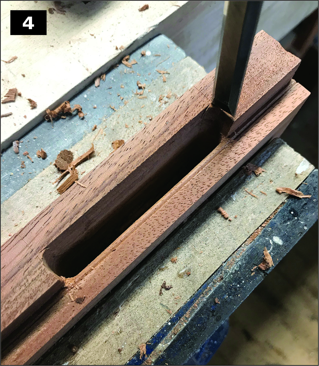
Without a horizontal mortiser or a vertical one, for that matter the next best thing is to set up your drill press with a fence and pencil lines instead of stops, then use a row of Forstner bit holes to take out the bulk of the mortise material. You will then switch to your wide paring chisel to clean up the inside faces and a 3⁄8″ mortise chisel to square the ends, as shown in photo 4. Be sure to go 1⁄8″ or so deeper than the tenon length, and check that depth everywhere so that there is no chance that the end of the tenon will bottom-out in Assemble the wings dry, as shown in photo 5, to confirm that all four openings for the glass are the same dimension. Your mortises might be a trifle long, and tenons could creep an eyelash one way or the other, resulting in unequal openings.

Under normal circumstances, this is not much of a concern, but the seam between glass and wood will be small, and irregularities will be quite evident, so be mindful. The best way to proceed is to take your wings to the glass shop and have the panes cut now. During glue-up, but before the glue sets, you can temporarily drop the glass into place and tap everything around slightly so that all the seams are equal. Set the glass aside until the varnishing is done, after which you will be ready to install the panes in their rubber bedding compound.
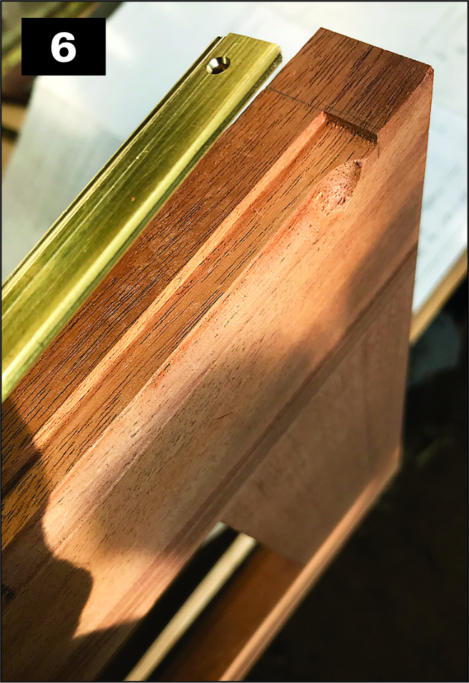
This is also a good time to create the drip edges, shown in photo 6, which will direct water seeping through the hinges into the gutters that you’ll cut in the strongback. The drip edges are made of strips of 1⁄8″ × 1⁄2″ brass flat stock 261⁄4″-long, which is let into, and flush with, the inside edge of each wing’s top rail, stopping short of the ends to accommodate the edge rounding later.
You will have to drill and countersink for brass screws, spaced about 3″ apart and as high on the strips as you can fit the countersunk holes. Cut the recess with a fenced router or on a router table and square the ends with a chisel. But before installing the brass, rout a 1⁄4″ cove at the edge of the recess, as visible in photo 6. This should stop about 1⁄8″ from each end of the recess. I like to varnish the wood behind such appliqués, and you might as well hit the cove at the same time. Bed the brass and screw it in place. Later, the recess for the piano hinge will be routed not only in the wooden edge but also into a bit of the metal drip edge.
Hatch Elements
Heavily tapered pieces always have fragile tips, edges, and interfaces. It is an unalterable maxim that no matter how perfectly cut and fit your joints are, any damage to the wood at the visible seams will make the entire joint look bad, and you simply cannot have that. So, start thinking about how you are going to protect delicate edges and tips until everything is glued up and safe. The first rule is to wait to cut a fragile edge until you have to. As you prepare to shape the sloped end pieces or dovetail the hatch’s corners, this means holding off on cutting any angles as long as you can. This is not only protective but also gives you square edges to measure and work from.
So, leaving everything square for the moment, knife in the side and end pieces’ inside (24″) and outside (261⁄2″) dimensions. Square the lines around and cut the pieces to length, giving yourself a little extra at each end to be planed off after the dovetail joints are assembled. Then cut the 5⁄8″ × 5⁄8″ rabbet into the inside bottom corner of each piece; these are the rabbets that will fit into a corresponding rabbet cut into the top outer edges of the grub. Put the vertical face of the hatch’s rabbets on the centerline and the top face equally dimensioned from the bottom. Do this on the tablesaw and clean up the saw marks with a rabbet plane. This rabbet is not as visually consequential as the ones in the wings, so there is probably no need to add a pass with a straight router bit.
With the strongback stock an inch or so longer than its final overall length, square it true and knife-in a vertical centerline on each end. “Knife-in” is a relative term. It gives you a tangible place to locate tools and other layout equipment, but you don’t want a cut to show on what is going to be a finished surface, so where appropriate knife very lightly or simply mark the line with a sharp pencil to be safe. In the case of the strongback, these ends will be machined or cut away, so you can be a bit more aggressive. Along the top and the underside, however, use only a sharp pencil to connect the end marks. (You’ll keep reminding yourself that someone lying on a berth below will study your work from that angle.)
Transfer the layout of the rest of the angles and faces of the strongback’s cross-section from your lofting to the hatch end pieces and to the ends of the strongback. The lofting on the end pieces should be done in such a way that the 45-degree angles of the strongback’s lower corners intersect the short, vertical outboard faces to leave the eventual intersection with the sloped top edges of the ends at least 1⁄8″, and preferably a touch more, below the top edge of the uncut stock. This is all in service of keeping interfaces sharp, clean, and safe.
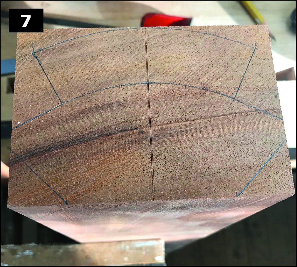
For the strongback, as shown in photo 7, start with the bevel corresponding to the top of the slope of the end pieces. Mark on that line the exact location of the points that represent the lower corners of rabbets that receive the wings. Square up from that point to mark the back of the rabbet. Measure out along the squared line a distance equaling the thickness of the wings to mark the rabbet’s upper corner. The top arch of the strongback has a radius of 3″, measured from the centerline at its lower edge. The lower part of the arch has the same radius, starting from the centerline 11⁄8″ below the top radius. Clamp a piece of wood flush with the strongback’s lower face, knife-in an extension of the centerline, and measure along it to give your compass a footing for marking these arcs.
One of the trickiest steps in this entire construction is fitting the strongback to the end pieces, with five surfaces that must mate perfectly. On the top edge of the hatch’s end pieces, mark a centerline with a sharp pencil and extend it down the inside and outside faces. Stand up the end pieces on the bench, square and spaced exactly according to the lofting, and place the strongback on top, with the centerlines aligned. Mark the locations of the lower corners of the strongback onto the top edges of the end pieces and knife them across with a square, then use a sharp pencil to extend them square down to what will be the finished depth of the joint, inside and out.
To maximize precision, you’ll do this cutting and fitting in stages. Transfer the layout of the angles and faces of the strongback’s cross-section from your lofting to the hatch end pieces. The lofting should be done in such a way that the 45-degree angles of the strongback’s lower corners intersect the short, vertical outboard faces at least 1⁄8″, and preferably more, below the top edge of the sloped end pieces.
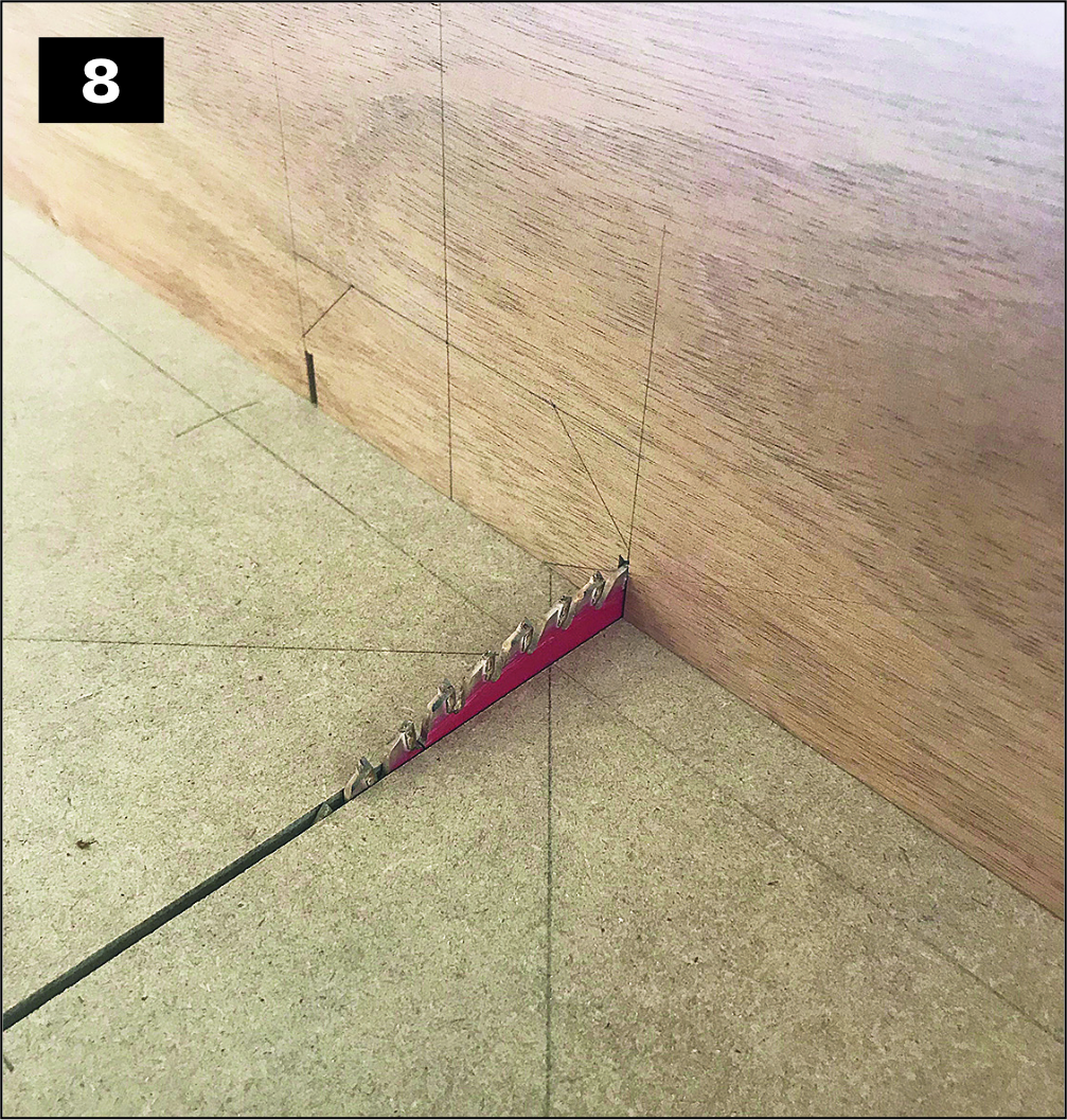
Knife-in the short vertical cuts you are going to make at the marks showing the width of the strongback. These will be the first cuts; make them with a fine dovetail saw or on the tablesaw, as shown in photo 8, but take care to terminate them exactly where the lofting indicates that they intersect the 45-degree angles. When the slopes are cut in the end pieces later, they will terminate in sharp points at the intersections with the strongback.
These points will be very fragile before the strongback is glued in place, so you will start your cutting and fitting with confidence with the end pieces left square.
Using a chisel or bandsaw, remove the waste between these two short vertical cuts along a straight horizontal line drawn a fraction above their termination points.
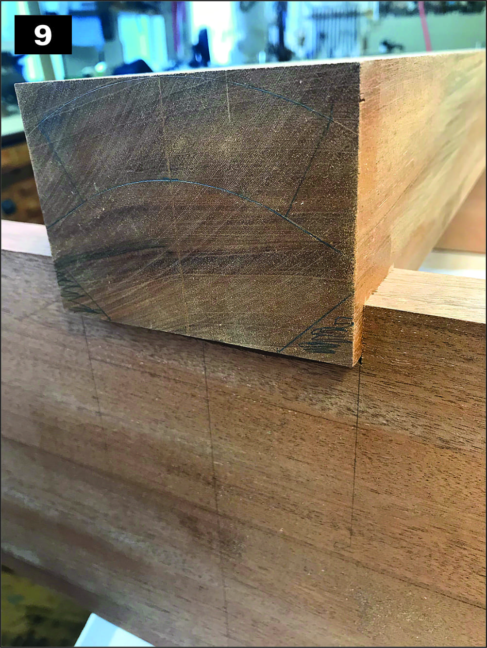
You are now ready for your first fitting of the strongback, as shown in photo 9. This should be a snug, “whisper” fit, not a “drive.”
After that fit is right, fit the strongback exactly centered lengthwise on the end pieces so that its overhangs at each end are equal. Square up everything and make sure your 24″ inside dimension of the hatch is true to the layout. Mark with a pencil on the faces of the strong back where it meets the inside and outside faces of the end pieces.
The sequence of tablesaw cuts to rough out each side of the strongback is shown in photo 10. While the piece remains squared, remove waste outside of the arched top’s 3″ radius by cutting a bevel (labeled No. 1) parallel to the bottom of the rabbet for the wings.
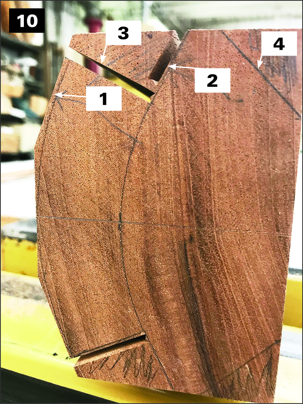
Next, use the same saw bevel to cut the bottom rabbet (labeled No. 2) in the photo. It’s a good idea to cut this 1⁄8″ proud of the line so that it can later be planed flush for final fitting the wings. Third, use the new bevel on the top of the piece to cut square to form the back rabbet (No. 3). Last come the 45-degree angle cuts, No. 4, on the bottom corners.
Plane off the saw marks on those bottom angles with a jack plane set fine so as to avoid changing the angle or taking off too much wood. But hold off on cleaning up the rabbet and finishing the top so you can do a bit of extra planing to make them flush with the sides when installing the wings.
Saw off a thin cross-sectional piece—about 3⁄8″ or so from each end of the strongback so that after the cuts are made it matches the length of the wings. Save these two off cuts, labeled for each end, and set the strongback aside. Next, cut the slopes on the end pieces on a bandsaw, slightly away from the line and then plane them by hand to the line. This establishes the fragile tips, mentioned earlier, that need to be protected.
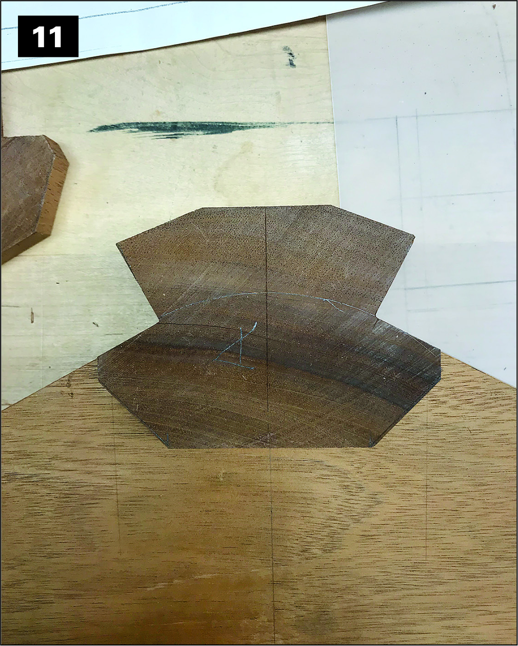
I tape some bits of waste wood over them just in case I drop a tool or accidentally tap them against the bench. Though you transferred the profile of the strongback to the end pieces from your lofting, you will now correct any inconsistencies into precise lines marking where to cut the notches in the end pieces to receive it. Working one end at a time, place the thin strongback offcut onto its corresponding end, as shown in photo 11, oriented the same way as when it was still attached to the strongback. Align it so that it lies along the lofted bottom line and the short vertical faces match those cut in the end piece.
Carefully knife its perimeter into the end piece on the outside. Keeping the offcut in the same orientation, repeat this on the inside of the end piece. On the bandsaw, cut out the waste close to the line and finish up with a paring chisel.
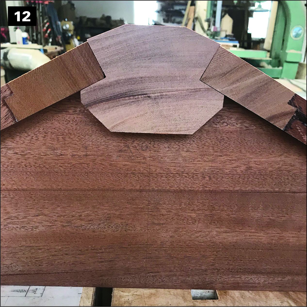
You will do well to slightly hollow the surface to ensure you have good contact with the outside edges, as shown in photo 12, particularly the top interface between the ends and the strongback, which is why you’ll be protecting those delicate points right up to the final assembly. When the fit is right, clamp the strongback in place and lay the wings in the rabbet, shimmed up with a thin piece of cardboard (not visible in the photo) between them and the slopes of the end pieces. This will give just enough clearance when finished so that the wings will not bind when closing.
Knife a line along their top edges into the back rabbet on the strongback. Plane the flat on the top down to the line to make a square corner, as shown in photo 12. This will give you a flat surface on which to register the router when cutting the hinge recess, which is shaped in the edges of both the strongback and the wings. While the wings are in place, trace the hatch’s outer perimeter onto their undersides with a pencil.
The Hatch Dovetails
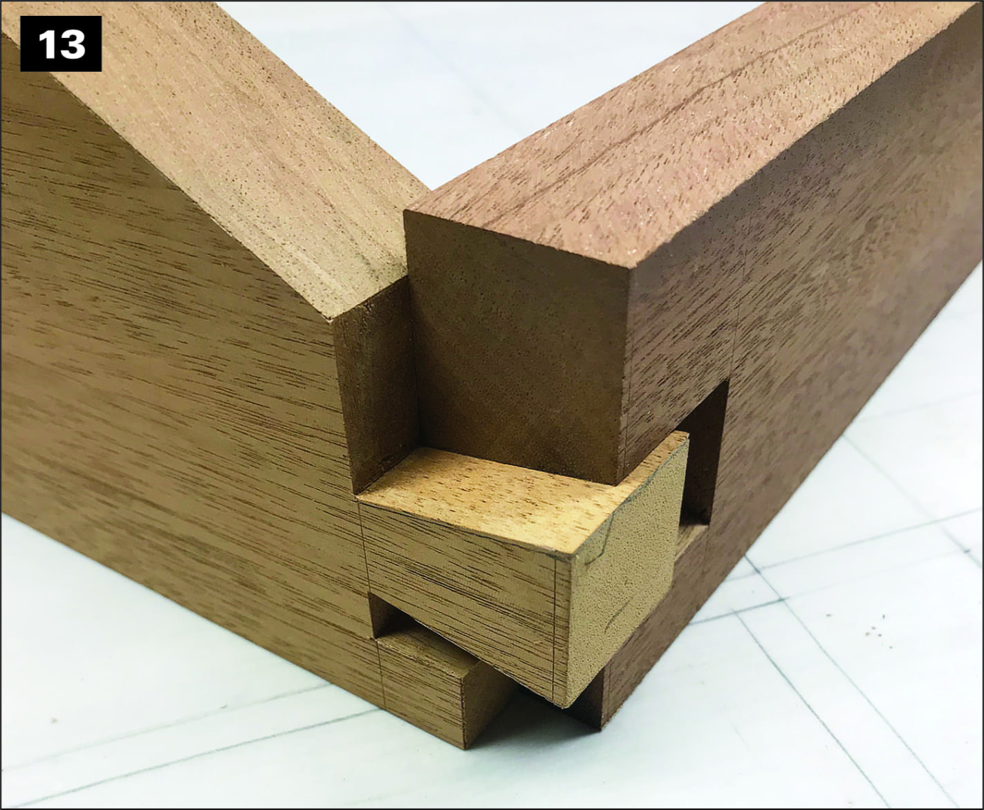
Before further shaping the strongback, make the hatch side pieces and dovetail them to the end pieces. As is usual for this type of joint, the dovetails are cut first, and they become the templates for laying out the pins. This hatch’s side pieces are low, and the bottom rabbet must be accommodated, so you really only have room for one big tail, as shown in photo 13.
Boat dovetails need to maximize strength, so they are a little different from their more aesthetic cousins in furniture joinery. Wide dovetails and thin pins may look best and are plenty strong for furniture, but on a boat we try to equalize strength by having approximately equal quantities of wood fiber, and thus strength, in both pins and tails. It makes for a somewhat clunkier look but assures maximum strength.
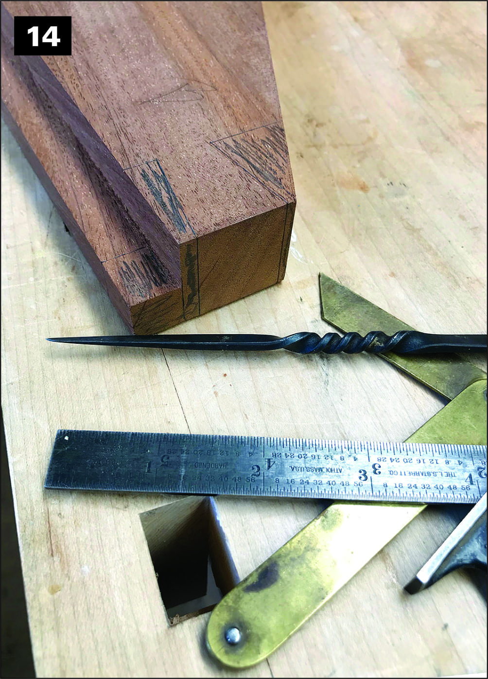
So, lay out your dovetails on the end pieces, as shown in photo 14, staying clear of the rabbets and the beveled top edge of the side pieces. Because the slopes of the ends are steep, you can bring the bottom edge of the dovetail layout up pretty high. The end of the rabbet on the end pieces must be cut to end up tucking just inside the rabbets of the side pieces.
If you are confident, you can lay this out and cut it along with the tail, but there is nothing wrong with leaving it a bit long and trimming it after the tail and pin are cut and the rabbet end can be brought up against the surface it has to mate with. If you are confident, all cuts can be made with a dovetail or back saw, but the tablesaw provides greater certainty to the cuts when setup is not too complicated.
Once the dovetails are cut, their profiles are traced with a knife onto the ends of the side pieces, which are still square. Again, the outer edge of the rabbet is off the surface, but since it is already cut to length (or just a dight longer) and its final resting place is already established by the rabbet on the side piece, you don’t have much to deal with. Square the layout to the line marking the inside of the hatch and cut with a dovetail saw, removing the waste with a chisel. I always darken what will be waste to doubly guarantee that I cut on the correct side of the line.
When you dry-fit this assembly, mark the slope of the ends directly to the side pieces and cut this bevel on the tablesaw. Make the cut as clean and close as possible, but leave the final lick with a plane until after assembly.
Rounding the Wing and Strongback Edges
First, while the edges of the wings and strongback are still square, set the piano hinges. Rout the recesses for them while there are still flat surfaces to run the fenced router along or to locate the piece on a router table. Use solid brass or stainless-steel piano hinges, with an open measurement of 11⁄2″. The hinges stop at least 5⁄8″ from the ends to account for the outside rounding. Cut them to length and use them to mark on both the strongback and the wing where the setback will stop.
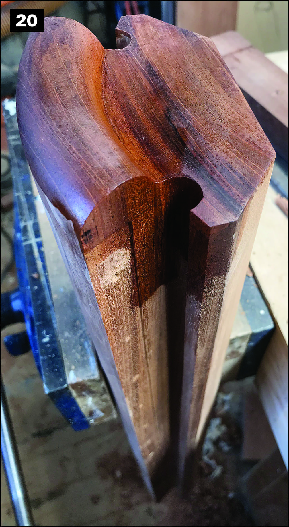
Cut the recess with a straight bit to a depth equal to the thickness of the hinge plate (as visible in photo 20), which will give you some clearance between the wing and the rabbet. If you want to go old-school and wrap the hinge with lightweight canvas, cut a little deeper. It is always a good idea to test these fits on sample stock first, so that you are confident of how everything is going to lie before cutting the real thing.
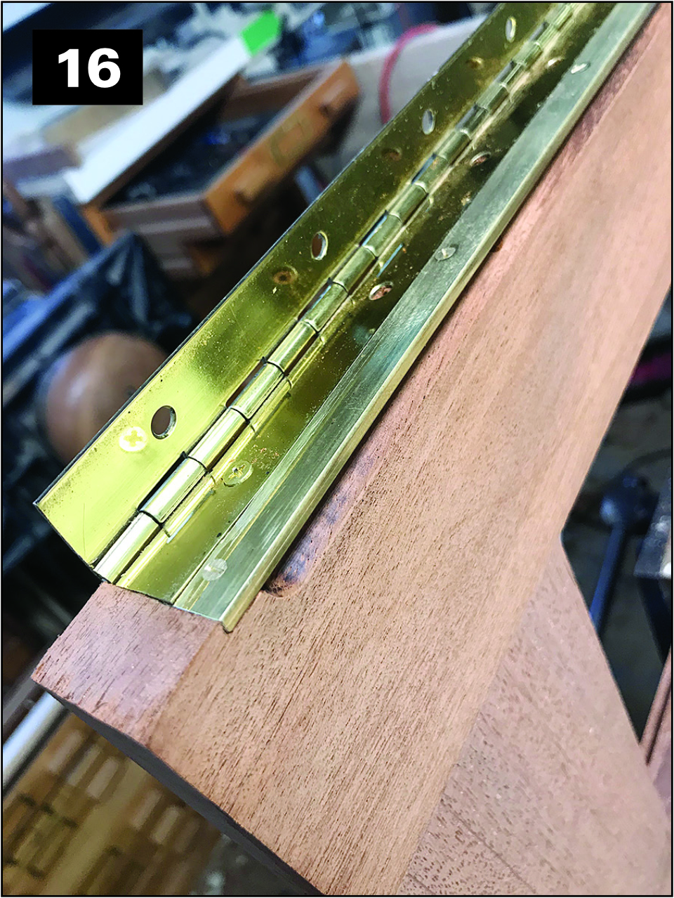
You will, of course, stop the router shy of the end marks and finish the recess square with a chisel. On the wings, the dimensions are such that the bottom of the hinge is just about even with the top of the brass drip edge, depending on how high you set the hinge. I wanted to keep it down tight, so I simply routed a tiny rabbet in the brass along with the recess for the hinge, as visible in photo 16. The carbide bit didn’t even notice, and I felt good about the minor water shedding overlap.
Next, continue shaping the wings. With a handheld router, router table, or shaper, round the edges of the wing ends. These pieces are 11⁄8″ thick, so unless you have a 9⁄16″ roundover bit, or have one specially made, you will use a 1⁄2″ roundover bit and follow-up with hand-planing by eye to get a nice, full radius.
The bottom stiles need special treatment: For the best look, the upper corner of that edge should be more of an oval, so when you are doing that follow-up planing, draw it farther back, to 3⁄4″ or even 1″, to create a nice gentle roll. The designer also suggests that the lower corner be made to a tighter radius, to keep water just that much farther away from the hatch opening. Rout that corner with a 3⁄8″ roundover bit. You’d need a French curve to properly draw that bottom edge’s profile, but you can shape it by eye.
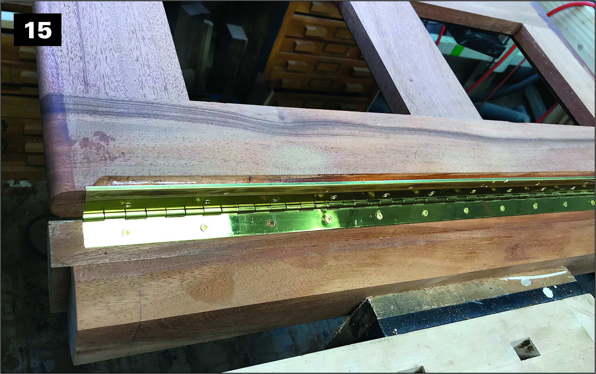
Screw the wings in place one at a time to the strong back. In the “closed” position, scribe the profile of their rounded edges onto each end of the back rabbet of the strongback, as shown in photo 15.
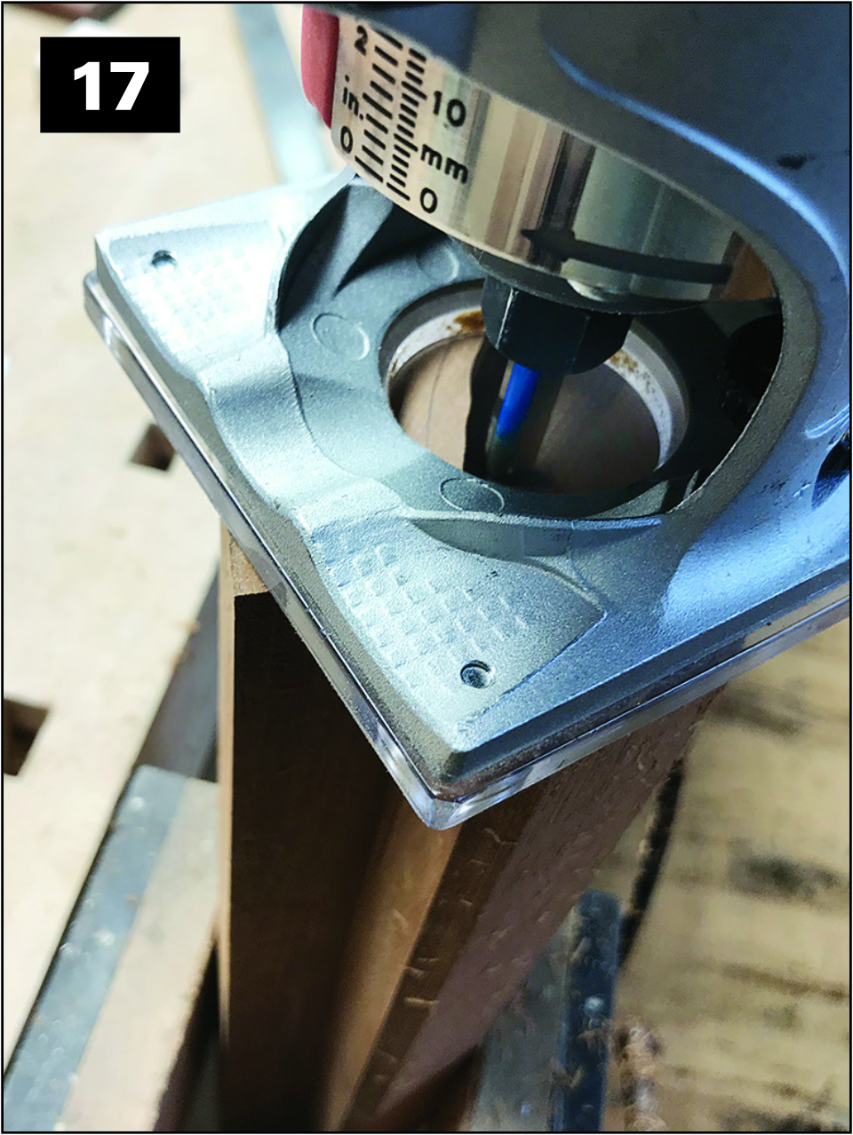
Next, take off the wings and return to shaping the strongback, starting by using a jack plane to round-over its top surface to its final radius, finishing with a scraper and sandpaper. Then use a router to cut back the end of the strongback below the curved lip to that it finishes no more than 1⁄8″ beyond the outside faces of the hatch end pieces, shown in photo 17. This can also be done with a good planer blade in a tablesaw, which leaves a bit more material in the concavity under the lip that must be routed or carved out. Either way, it’s up to you.
After that is completed, but before the ends are rounded over, rout the gutters, which are visible in photo 20, with a 1⁄2″-diameter cove bit, making its edge 1⁄32″ or so from the back of the rabbet.
For rounding the top corners of the strongback’s arched ends, you could use a router with a 1⁄2″ round over bit, but you are going to have to cut to the lower radius at each end with edge tools, so you might as well do the same on the top. A spokeshave works well for this, working in from both ends of the curve so as to avoid any breakout. Work to the line made by tracing the edges of the wings and finish up with a fine rasp or file to the point that you are happy with the rounding.
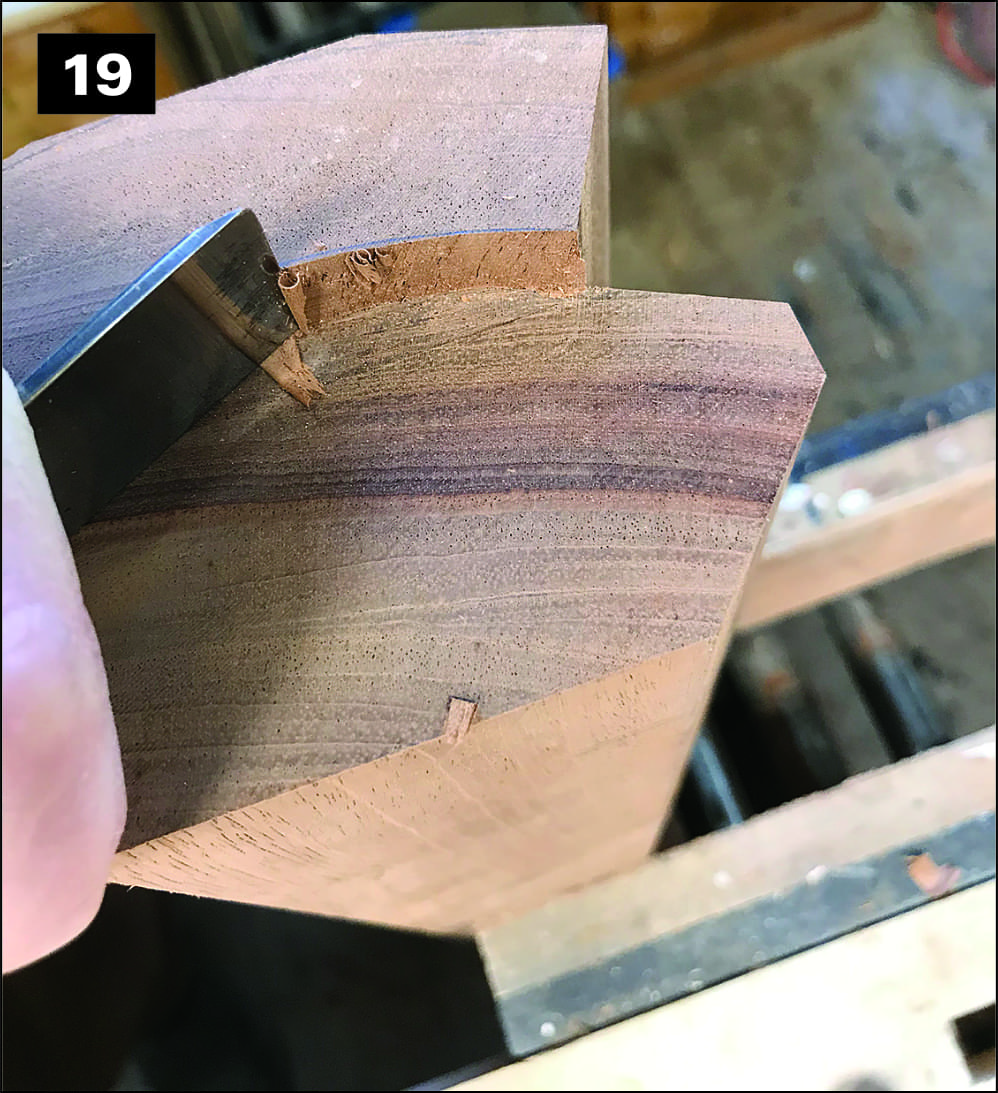
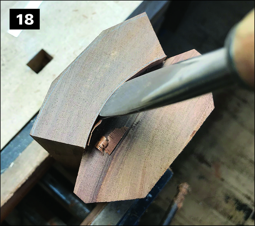
Unless you have an extensive set of carving tools, including back-bent gouges, you are simply going to have to slowly work the lower radius up with chisels, as shown in photos 18 and 19, and round it with a paring chisel flipped over onto the bevel. Take your time, put a strong light on the work, and look at it from every angle until your eye tells you that you are close.
It does not hurt to make a hardboard template of the radius; use a 11⁄8″ Forstner bit to drill it out and then cut in half and trim the bottom edge to account for the 1⁄8″ protrusion of the strongback. Sand out the chisel facets, and there you have it. Photo 20 shows the finished strongback.
Bringing It All Together
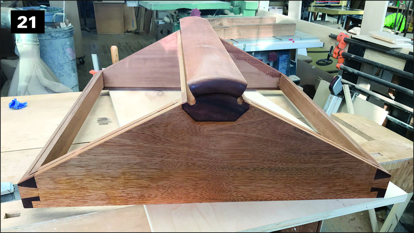
For the final assembly, first glue the hatch’s end pieces and sides together, as shown in photo 21. After the epoxy sets, trim off the dovetails and pins to finish off the joints. Before gluing the strong back in place, however, take advantage of the square edges and clear access to rout grooves on the center lines of the top edges of the end and side pieces. Make these stop 1⁄4″ shy of the strongback opening and the intersection of centerlines at the lower corners. You can leave all the slots round at their ends and round off the splines when fitting them, or square the ends with a 1⁄8″ or 3⁄16″ chisel and leave the splines square—your choice.
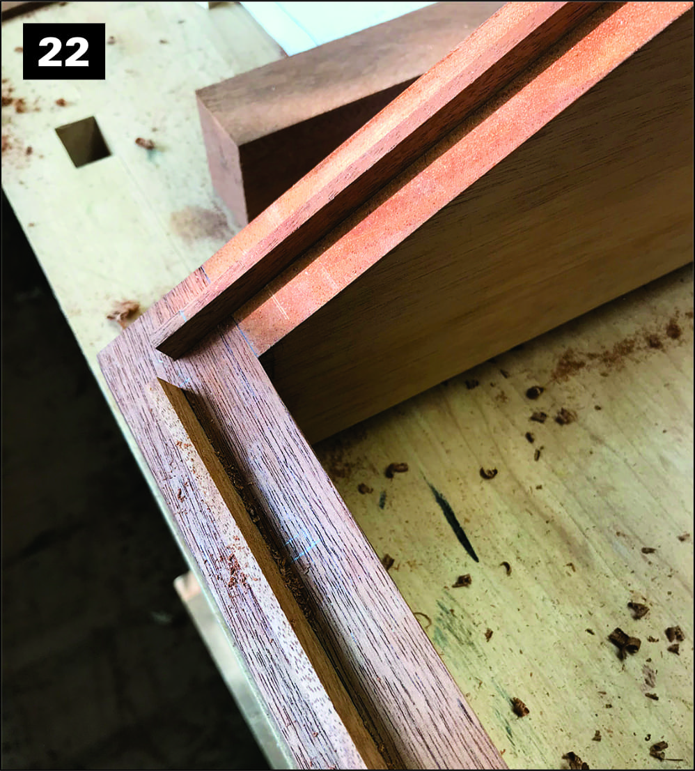
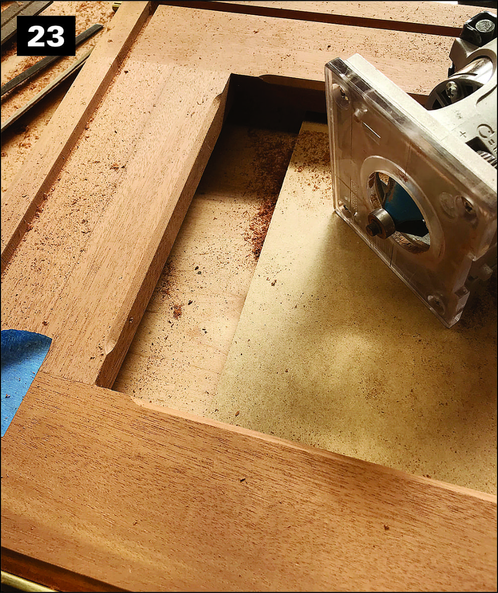
Make splines out of stock that fits snugly in the slots and sticks up a little more than 3⁄16″ and glue them in as shown in photo 22. You can leave them square, since it will be easier to shape them in place. Referencing the perimeter pencil lines previously drawn on the undersides of the wings, transfer the exact positions of the spline centerlines to guide the routing ofcorresponding3⁄8″-widegrooves in the wings, as shown in photo 23. (This is a good time to also rout chamfers on the inside edges, stopping short of the corners, also visible in the photo.) The grooves receive the gaskets that the splines press against when the wings are closed. Rout the grooves to an appropriate depth, which is dependent on your choice of gasket material.
They should be a touch long at the hinge ends. They should also be continuous at their lower corners, which will require stopping your routing short of the corners and finishing up with a chisel. I found great gasket material, a medium-density silicone sponge rubber, on Amazon. It is compressible and not too hard, and the closed-cell silicone should have a long life.
It comes in a sheet that requires cutting to dimension and lengths with a razor blade, but it worked like a charm. If you have a better solution, by all means use it.
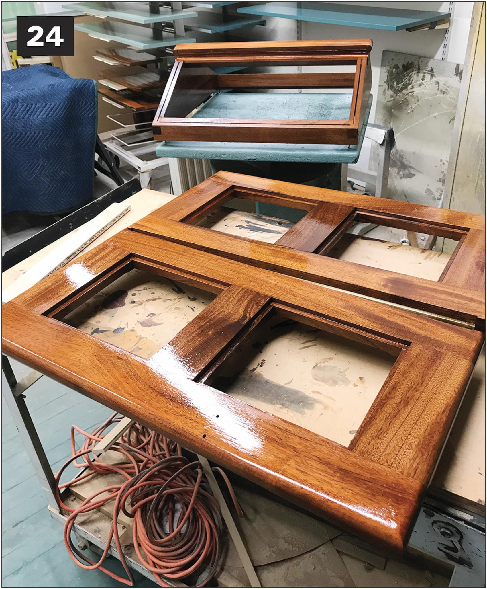
You will want to have it just contact the splines with approximately 1⁄16″ compression. Too much compression can keep the wings from closing all the way. For me, this meant a groove depth of ¼”, and slicing the ½” rubber in half with a simple jig after cutting 3⁄8″ wide strips. Set the gasket strips aside for final installation. Next is varnishing (photo 24), and after that is done, the gasket can be installed with a little contact cement and the plate glass panes can be set in the wings.
The glass is bedded in a heavy-duty black silicone that will highlight the interface with the mahogany. The panes will come with a slight polished chamfer that should stand just proud of the surface. The 3⁄8″-deep rabbet will allow you to slightly shim it in the silicone to the exact position. You can do this by eye with tiny bits of veneer buried in the silicone or set four No. 2 brass wood screws in the corners and adjust them until the glass sits perfectly. Silicone does the rest. Pro-tip: tape every- thing off before applying silicone.
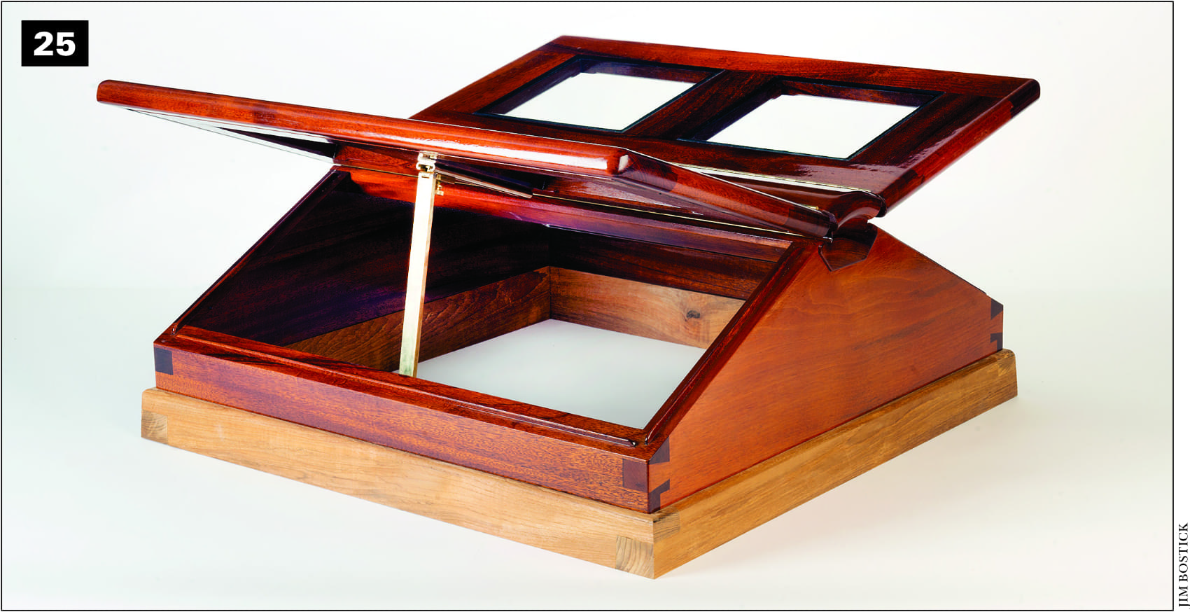
The butterfly skylight can be opened on both sides and is designed to be detached, lifted off the teak grub, rotated 90 degrees, and reset to take best advantage of the prevailing breeze. The author also designed and fabricated his own hardware.
Tape to the top of the chamfer, and when you are (quickly) wiping down the excess squeeze-out, let the silicone ride up the surface of the chamfer. This is much easier to clean up and the look is the same as if you had laboriously worked to stop the silicone at the bottom of the chamfer. The skylight is now ready for installation, using your choice of off-the-shelf or custom-made hardware.
This article was originally published in WoodenBoat No. 282, September/October 2021.
Mike Podmaniczky served as furniture conservator for the Winterthur Museum in Wilmington, Delaware, for many years before teaching conservation and historic woodworking practices at West Dean College in England. Earlier, he was foreman and vice-president of William Cannell Boatbuilding Co. in Camden, Maine. Now an independent conservator and craftsman, he lives on the North Shore of Boston.